I have been playing around with Multi-Site NSX now for a few weeks and I have to say…it has been a lot of fun! You want a good refresher on routing? Then attempt setting this up! Multi-site routing is something I have dealt with in my past. That experience helped me a lot here with understanding which network needs to go where and most importantly HOW do I get from Point A to Point B. Fun stuff!
For the longest time my lab environment contained a single-site instance for NSX; multiple vSphere clusters to separate compute, edge and management workloads. Then I finally decided to stand-up a secondary site and call it DR. Could it be used for an Active/Active data center scenario? Sure…if I wanted to. I had limited resources but just enough to stand up a secondary site and call it DR. If I had enough resources to fully mirror my primary site I would.
I wasn’t able to find a whole lot of information online on how to tackle setting up Cross-vCenter with Multi-Site NSX. The guides and articles I did find discussed a lot at a high-level but never got into the deep detail of how to accomplish this task. In my opinion, the best document I found covered NSX and SRM. Even though I am not deploying SRM in this environment (yet) the guide did provide some great insight to the multi-site architecture.
Here are a few documents that you should read thoroughly to help get you started and get a better understanding of the situation you are about to dive into.
Cross-vCenter NSX Installation Guide (PDF)
Disaster Recovery with NSX and SRM (PDF)
READ THOSE DOCUMENTS COVER TO COVER…..RTFM all day!!! 🙂 I have more links at the very bottom of this page that will also help.
So back to my INITECH lab environment and setting up Multi-Site NSX (aka Cross-vCenter NSX). This environment is 100% nested. Everything including the pfSense virtual appliance routers that I am using.
You will find a similar layout and design in the VMware Hands On Lab (HOL-1725-USE-2) VMware NSX Multi-site DR with SRM as well as other awesome blog posts out there. You will find this procedure is fundamentally the same with a few minor twists that all depend on what you are ultimately trying to accomplish whether it be short-term or long-term.
What am I looking to achieve here? Let’s first review what we are working with in each site.
- Site A is the primary site; Site B is the secondary (DR) site.
- Site A contains three (3) vSphere Clusters; Management, Edge and Compute.
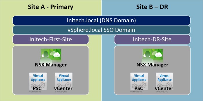
- Site A NSX Manager (nsxmgr-01a) which has a 1-to-1 relationship with the PSC and vCenter Server appliances in Site A.
- Site B contains a single DR cluster.
- Site B NSX Manager (nsxmgr-02b) which has a 1-to-1 relationship with the PSC and vCenter Server appliances in Site B.
- The PSC appliances (one in each site) are federated by the same SSO domain but operate in separate SSO sites.
- The vCenter Server Appliance is used for all PSC and vCenter instances; the NSX Manager is a separate virtual appliance deployed from an OVA.
Here is a small conceptual diagram of the environment for the vSphere & NSX Components.
Planning the Environment
This is a very critical step that you do not want to ignore. Use this time to get your ducks in a row and get organized. You have probably heard the saying…
“fail to plan…then plan to fail!”
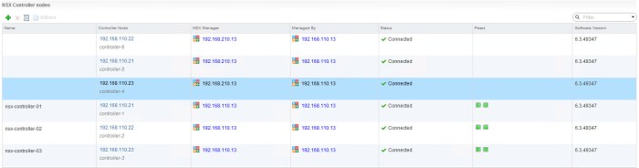
Words never spoken truer! I’m specifically highlighting this because I did rush some things to get this part of my lab up and I overlooked the settings in my DR site VTEP IP Pool. Long story short, it caused a lot of problems. I spent a lot of time thinking it was something I did wrong in my NSX Universal Logical Router or Switches and it was never the case. The Universal Controllers could not communicate with the ESXi hosts in my DR site and the “Control Plane Agent to Controller” was constantly DOWN (see below).

So…don’t get ahead of yourself like I did (even if you have done this procedure 100x). Double and triple check your work and use a run book. I like using spreadsheets so that is what I recommend using. I clearly didn’t stick to my own words here and it got me in trouble HAHA! So learn from my mistake of rushing and getting ahead of myself!
I was spinning my wheels for a few hours with this I had to have another set of eyes assist me. So I decided to reach out to the NSX Legend Elver Sena Sosa (VCDX 154). He helped me refocus my investigation at Layer 2 first before getting to Layer 3. This lead to finding the error being generated above and resolving the issue that existed between the NSX Controllers and the DR site ESXi hosts.
Anyway, moving on! Here is a quick summary of my NSX environment. Specifically the components (roles) and their TCP/IP address(es). Everything in vSphere is running 6.5 and the NSX environment is running version 6.3.
Initech – Site A (Primary Site)
Everything is part of the ‘initech.local’ DNS (AD) domain. All IP addresses use a /24 netmask and a gateway of 192.168.110.1.

Initech – Site B (DR Site)
Everything is also a part of the ‘initech.local’ DNS (AD) domain. All IP addresses use a /24 netmask and a gateway of 192.168.210.1.

Now let’s take a quick look at a very basic logical diagram with a few physical characteristics for the environment. As you can see each Site will have it’s own Platform Services Controller (PSC), vCenter Server and NSX Manager. The NSX Manager in each site is registered with the local PSC (Lookup Service URL) and vCenter Server. The Universal NSX Controllers will only exist in Site A. A new set of controllers are not deployed in Site B.

Configure NSX Manager
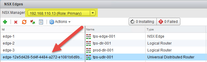
Once the NSX Managers are deployed and configured in both sites our next goal is to assign Primary and Secondary roles to them. Simply log into the vSphere Web Client UI, select Networking & Security and then select Installation. On the Management tab you should see both of your NSX Manager appliances and the vCenter Server that they are associated with. Follow this procedure to configure the NSX Manager roles and other tasks to prepare the secondary site.
- From the Management tab, select the Actions menu and then choose the Assign Primary Role option. When the process completes the primary sites NSX Manager will assume the Primary role; the secondary NSX Manager will have a status of ‘Standalone’ in the role column.

- Select the Actions menu again and then choose the option Add Secondary NSX Manager.

- Next you will be prompted for the secondary NSX Manager’s credentials. Enter the credentials and click OK.

- When the process completes you will see the number of NSX Controllers increase; however if you look at the Controller Node column you will notice there are three (3) instances when you notice the IP addresses. Reference the NSX Manager column and here you will see the IP addresses of both the Primary and Secondary NSX Managers.
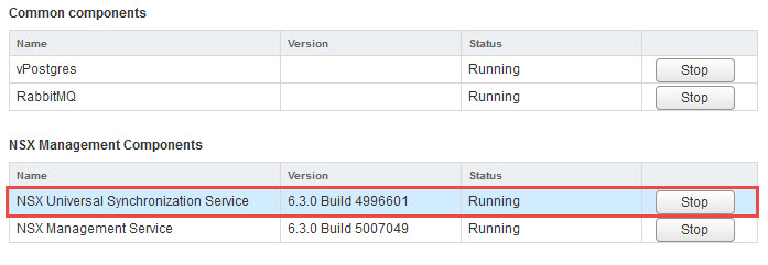
- Next we need to verify that the NSX Managers have started the NSX Universal Synchronization Service. To view this information simply connect to each of your NSX Managers from a web browser and verify that the following service has a status of RUNNING.
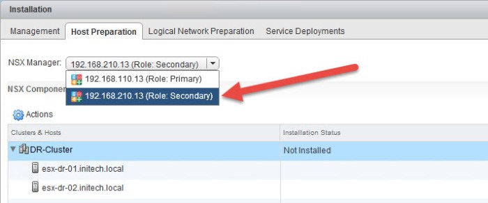
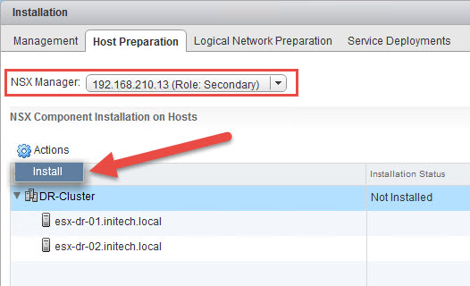
- Next we need to prepare the ESXi hosts in the secondary site. In this case my DR site where I have only two (2) ESXi hosts. Select the Host Preparation tab and then choose the secondary NSX manager from the drop down menu.
- Select the cluster and then from the Actions menu select Install.
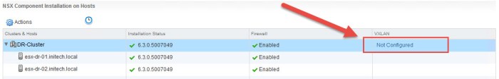
- Wait for the installation to complete. Next select the Not Configured link in the VXLAN column.
- In the Configure VXLAN Networking dialog box, select the vDS switch from your environment, specify VLAN, MTU size and then select Use IP Pool. I configured my VTEP IP Pool prior to this procedure. Just make sure the VTEP IP Pool range of addresses is in a separate network (VLAN) segment and not from the same management network segment that your hosts are using.

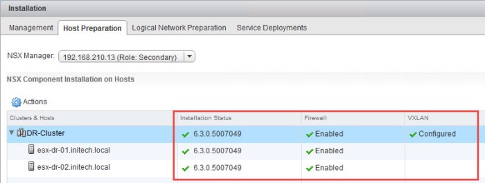
- Once the VXLAN is configured on the hosts everything should have a green checkmark on the Host Preparation tab.
- (Next 2 Steps are OPTIONAL) I am going to configure my local Transport Zone for my DR site. You do not have to do this if you are going to solely use Universal Logical Switches here but I’m doing this because there are some basic workloads that I want to run here only in my DR site. First select Segment ID and provide a range for your local Segment ID Pool that does not conflict with your primary sites local segment ID pool. Next, on the Logical Network Preparation tab, select Transport Zones and then select the plus (+) sign.
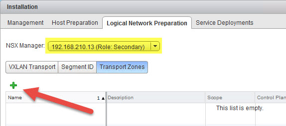
- In the New Transport Zone dialog box I enter some information about the new local transport zone in my DR site and then select my DR cluster and click OK.

That completes the steps for preparing your NSX Managers in both the primary and secondary sites for mutli-site NSX operations. Next I am going to walk you through the required steps for creating a Universal Transport Zone.
Create Universal Transport Zone
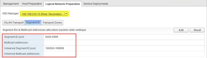
Next thing we need to do is create a Universal Transport Zone that will span across the two sites and include my vSphere clusters. Before doing so we must create a Universal Segment ID Pool. This pool is separate from the local Segment ID Pool. Here is a summary of all of my Segment ID Pools (local & universal).
Site A (Primary) - Segment ID Pool:  5000-5999
Site B (Secondary - DR) - Segment ID Pool:  6000-6999
Universal Segment ID Pool:  100000-199999
The Universal Segment will span both sites whereas the other pools are local to their respective site. Let’s create the Universal Segment Pool.
- Select the Logical Network Preparation tab and choose the primary NSX Manager from the drop down menu. Click the Edit button.
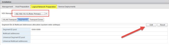
- In the Edit Segment IDs and Multicast Address Allocation dialog box enter the Universal Segment ID Pool range that you wish to use. I will be using the 100000-199999 range here. Click OK.

- Verify that the new Universal Segment ID Pool appears in the summary.
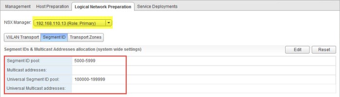
- Select the drop down menu and choose the secondary NSX Manager. Notice the Universal Segment ID Pool automatically appears. You do not have to create the pool on the secondary manager.
- Next need to create the Universal Transport Zone. First select Transport Zones and then choose the primary NSX Manager from the drop down menu. Click the plus (+) sign to create the new zone.

- In the New Transport Zone dialog box enter a name for the Universal Transport Zone, select the replication mode and then choose the clusters that will participate in the zone. Lastly, check the box for Mark this object for Universal Synchronization. Click OK when ready.

- Verify that the new Universal Transport Zone has been created on the primary NSX Manager.

- Choose the secondary NSX Manager from the drop down menu. The new Universal Transport Zone should appear. Click the Connect Clusters icon.

- In the Connect Clusters window, check off the clusters in the secondary site (or DR site) that you want to connect to the Universal Transport Zone and click OK.

That completes this step. You now have two NSX Managers deployed, Universal Segment ID Pool is created and the Universal Transport Zone that spans across the two sites now exists. Next we will create some Universal Logical Switches and Universal DLRs.
Universal Logical Switches
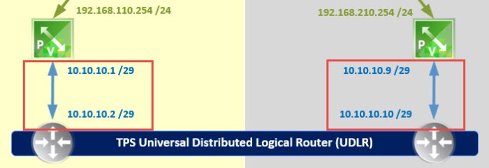
During this phase we will create a handful of Universal Logical Switches (ULS). These network segments are going to have a TCP/IP segment associated with them and connectivity will be managed by a ULDR. The ULDR will depend on the local ESG (Edge Services Gateway) that is deployed separate in each location.
The ESG in my primary site is: tps-edge-001
The ESG in my secondary site is: dr-tps-edge-001
We establish connectivity from the ULDR to the ESG’s by creating a “Transit” ULS. The transit networks are nothing more than a ULS being used to establish connectivity from the ESG to the ULDR. Simple as that. Our first two Universal Logical Switches that we are going to create are going to provide this connectivity for us.
I only have to create the ULS once on my primary and it will automatically synchronize with the secondary. So there is no need to repeat this multiple times.
- From Networking & Security in the vSphere Web Client, select Logical Switches. Verify that the primary NSX manager is chosen at the top. Click the green plus (+) sign.
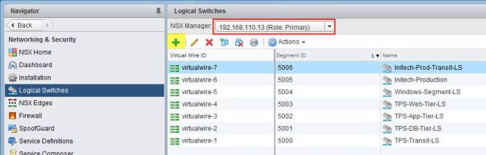
- In the New Logical Switch dialog box enter the name of the ULS that will be used as a ‘transit’ network between the Site-A ESG and the ULDR. Click Change next to Transport Zone. Select the Universal Transport Zone in the Transport Zone Settings dialog box that will appear (not pictured below) and click OK.

- Verify everything before click OK. The ULS will then be created.

- Verify that the Universal Logical Switch now appears in inventory. The ULS will have a Wire ID and Segment ID associated with it.
- Repeat Steps 1 through 4 again to create a second Transit Network for Site B. When you are finished the Logical Switch inventory should look something like this.
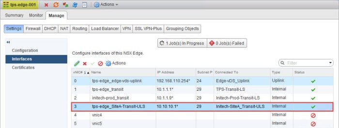
- Next we need to configure a LIF on the Site-A ESG that will connect to the new Site-A Transit ULS. Navigate to the ESG in your inventory and from the Settings > Interfaces menu select and available LIF and click Edit. Provide a name for the LIF, select INTERNAL for type and then select the Site-A Transit ULS. Configure the IP address on the interface just as it is depicted in the diagram.

- Verify that the interface on the ESG has been created and the status has a green check mark indicating that it is connected.
- Next repeat Steps 6 and 7 but do this on the Site-B ESG. In this case I am going to my ‘dr-tps-edge-001’ ESG and configuring a LIF for the Site-B Transit ULS. When I am finished I should see something like this.

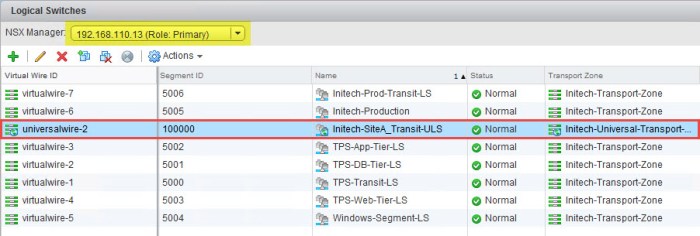
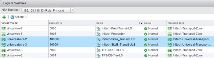
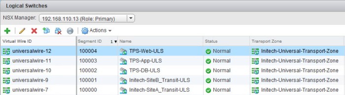
- Lastly I am going to create my three (3) Universal Logical Switches that I will use later for my workloads. We are not going to connect them yet because we still have to deploy the ULDR which will provide the LIFs for connectivity. So here I repeat Steps 1 through 4 above and create three more ULS, one for each tier; DB, App and Web. I will have a total of five (5) ULS when I am finished. Two of them will be used for my transit connectivity and the other three will be for my TPS application.
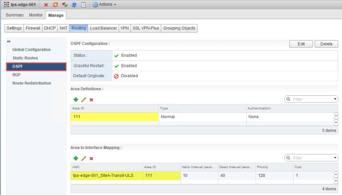
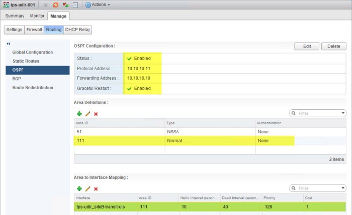
After completing all of the steps above to connect the ESG to the new Transit ULS networks you will need to configure routing on the ESG. The OSPF configuration on my ESG (tps-edge-001) will require a new OSPF Area ID that will be assigned to an interface (Area to Interface Mapping). The OSPF Area ID that I am using for my ULDR deployment is 111.
Universal Logical Distributed Router (ULDR)
The next step is probably the longest phase (the most steps) during the entire process as we have to deploy a new NSX edge instance as a ULDR. Deploying the ULDR is no different than deploying any other logical router, just a few different steps during the deployment wizard.
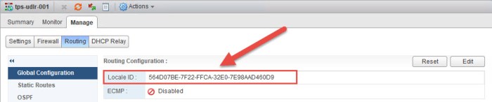
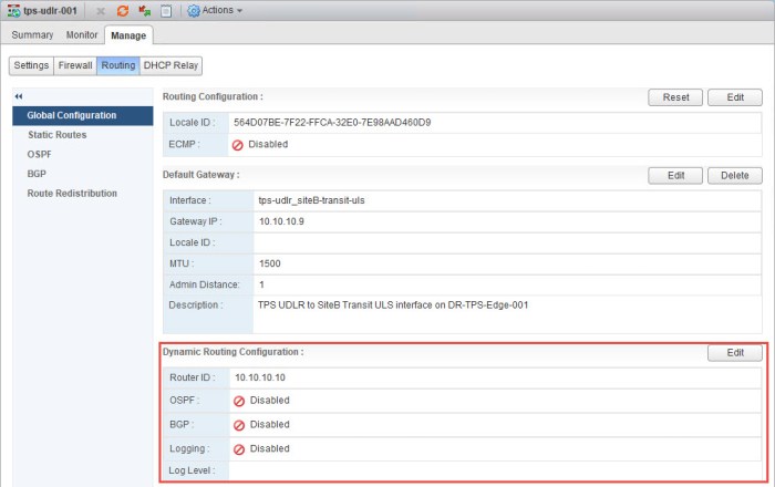
Before we begin we need to collect some information that will come in handy later. We need to record the Locale ID for the NSX Manager appliances in each site. From Networking & Security, select NSX Managers at the bottom left. Select your primary NSX Manager and on the Summary tab you will see a long ID #. Record this information in notepad, a spreadsheet…somewhere in your runbook. The ID’s for my two NSX Managers are highlighted in the graphics below.
The Locale ID’s will allow us to bring “location awareness” to the routing table. We are going to apply them to the ULDR’s in each site in a moment.

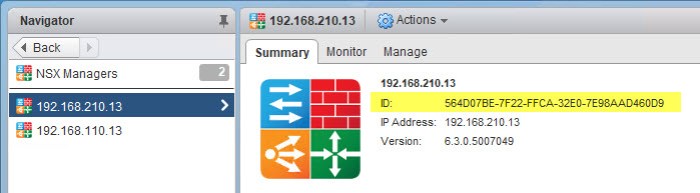
NSX Manager Site A: nsxmgr-01a - 192.168.110.13
Locale ID:  564D4685-488B-7291-F32A-606B42D1A5A5

NSX Manager Site B: nsxmgr-02b - 192.168.210.13
Locale ID:  564D07BE-7F22-FFCA-32E0-7E98AAD460D9
Let’s get started on the ULDR deployment.
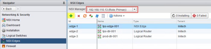
- From Networking & Security select NSX Edges and click the green plus (+) sign. Make sure the primary NSX Manager is selected. The New NSX Edge wizard will appear.
- On the Name and description page select the Universal Logical (Distributed) Router option, check the box to for Enable Local Egress, provide a name, description (optional) and tenant. Lastly check the box to Deploy Edge Appliance and click Next.

- On the Settings page enter the credentials that you want for the new edge appliance and then check the box to Enabled SSH access. Enable FIPS mode is also optional. If you don’t enable either here do not worry because you can always enable them again later. Click Next when ready.

- On the Configure deployment page select the data center from the drop down menu. Next click the green plus sign and proceed with selecting a location to deploy the control VM for the ULDR. I have a separate NSX Edge Cluster so I will be deploying my ULDR control VM there. Click Next when ready.

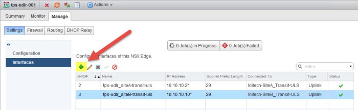
- On the Configure interfaces page select an uplink for the HA Interface Configuration. Here I chose a distributed port group on my vDS. I did not configure an address on this interface but you can if you wish. In the Configure interfaces of this NSX Edge portion (bottom) create two (2) interfaces for the ULDR. The first interface should connect to the Site A Transit ULS that we created earlier; the second interface should connect to the Site B Transit ULS. The goal here is to create the two uplink interfaces that the ULDR will use to communicate with the ESG. Click Next.

- On the Default gateway settings page clear the check box for Configure Default Gateway for now. We will change this later. The only reason I choose not to configure this here is because the ULDR instances in each site will use a different default gateway. It’s my preference to configure this manually later. Click Next.

- Review the information on the Ready to complete page and click Finish. The appliance will begin to deploy.

- Once the ULDR control VM is deployed it will appear in the NSX Edges inventory.

- Next we are going to assign the Locale ID that we gathered earlier and apply this to our new ULDR in Site A. Simply double-click the newly deployed ULDR then navigate to the Manage > Routing > Global Configuration. Click the Edit button. Paste the Locale ID of the Site A NSX Manager into the Edit Routing Configuration window and click OK. Click Publish Changes.

- Confirm the Locale ID has been applied to the ULDR in Site A.

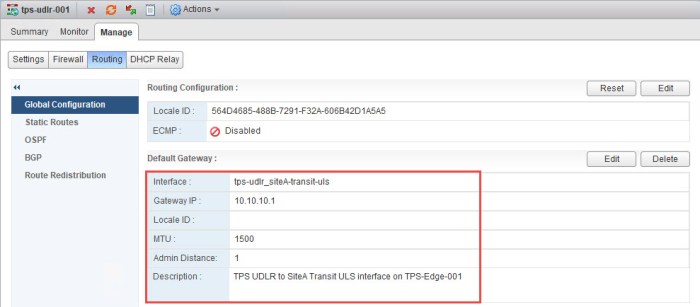
- Next we need to apply the Default Gateway. Click Edit.
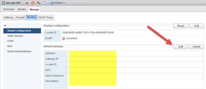
- Select the Site A Transit ULS link, set the default gateway for the interface and click OK. The static address for the Gateway IP here is the IP address that we assigned on the vNIC earlier on the ESG that connects to the Site A Transit ULS.

- Confirm the Default Gateway has been set for the ULDR.
- Next we will set the Router ID for the new ULDR. Click the Edit button and choose the Site A transit interface (uplink) and click OK. Confirm the Router ID has been applied. The Router ID should assume the IP address that has been set on the uplink interface that we created during the deployment.

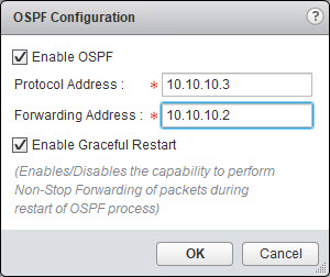
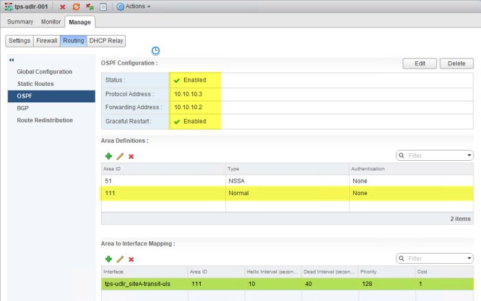
- Next we will configure OSPF on the ULDR. Select OSPF from the Manage > Routing page. Click the Edit button in the top right and enter the information for your ULDR.
- Create the same Area Definition (Area ID) and the Area to Interface Mapping. I used Area ID 111 on my ESG for this network so I must use the same Area ID here. I am going to map this Area ID to my Site A Transit ULS uplink interface.
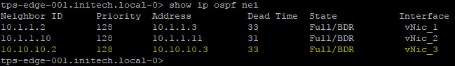
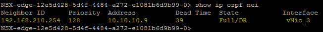
- Give the ULDR and the ESG a moment to form their adjacency. Open a Putty (SSH) session with each and execute the following command to verify everything.
show ip ospf neighbor

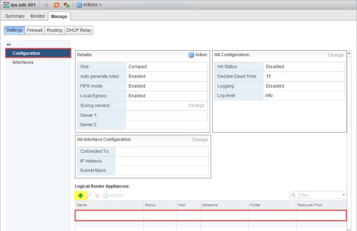
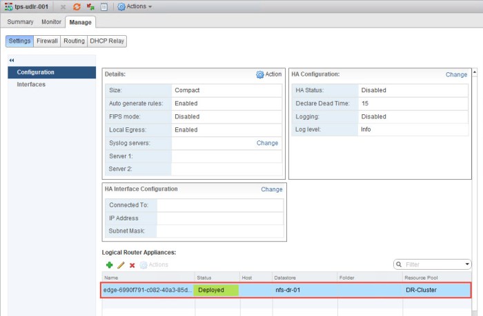
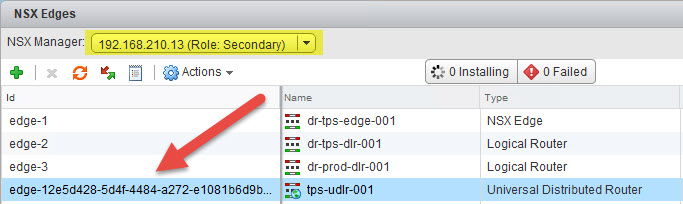
- Next we need to deploy the ULDR control VM in Site B. Simply navigate back to NSX Edges and select the secondary NSX Manager from the drop down menu. Then double-click the ULDR in the inventory.
- Navigate to the Manage > Settings >Configuration of the ULDR and you will immeidately notice there are NO control VM appliances deployed. Click the green plus (+) sign.
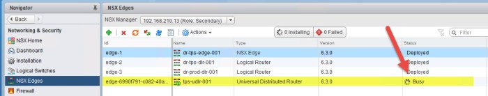
- Select the location in Site B where you want to deploy the ULDR control VM. Click OK when ready. The control VM should begin deployment.

- Briefly navigate back to the NSX Edges inventory page for the secondary NSX Manager and you should see a ‘Busy’ status for the ULDR.
- Once the appliance is deployed you can then return to the Configuration of the ULDR in Site B and you will now see the appliance status says Deployed.
- Just as we did with the ULDR in Site A, we must repeat these steps for Site B. First we must apply the Locale ID of the Site B NSX Manager to the Site B ULDR. Navigate to Manage > Routing > Global Configuration and click Edit. Enter the Locale ID for the Site B NSX Manager and click OK.

- Confirm the correct Locale ID has been applied.
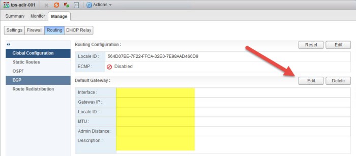
- Next we need to apply the default gateway. Click the Edit button.
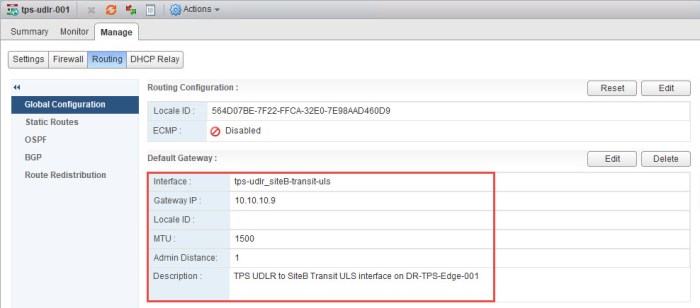
- The IP address (10.10.10.9) is assigned to the LIF (vNIC) on my ESG in Site B that connects to the Site B Transit ULS will be the gateway for this ULDR.

- Confirm the correct default gateway has been set.
- Next configure the Router ID for the Site B ULDR. This will be the uplink interface on the ULDR that connects to the Site B Transit ULS.
- Next we will configure OSPF on the ULDR just as we did with the ULDR in Site A. Select OSPF from the Manage > Routing page. Click the Edit button in the top right and enter the information for your ULDR.
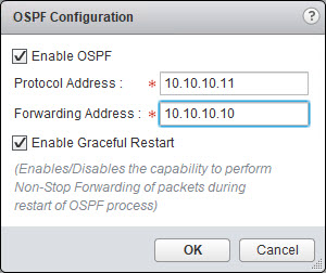
- Then I will complete the OSPF configuration on the Site B ULDR just as I did with the Site A ULDR. I am going to use the same Area ID 111. The Area to Interface Mapping will be the uplink interface that connects to the Transit B ULS.
- Confirm that the Site B ESG and the ULDR have formed their OSPF adjacency. Open a Putty (SSH) session and execute the following command.
show ip ospf neighbor

- Next we need to create a Static Route on the ULDRs so they can communicate with the physical network of the opposite site. Navigate to NSX Edges and then select the primary site NSX Manager from the drop down menu. Double-click the ULDR.
- Navigate to Manage > Routing > Static Routes. Click the green plus (+) sign.
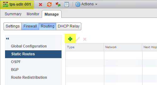
- In order for the ULDR in Site A to get to Site B’s physical network I need to tell it to use the Site B Transit ULS uplink interface. Click OK and then click Publish Changes.

- Next navigate to the ULDR in Site B.
- Then navigate further to the Manage > Routing > Static Routes page and click the green plus (+) sign.

- In order for the ULDR in Site B to get to Site A’s physical network I need to tell it to use the Site A Transit ULS uplink interface. Click OK and then click Publish Changes.

Universal Logical Switches for VMs
Next I am going to quickly create my Universal Logical Switches (ULS) for the 3-tier appliance that I want to deploy there. I will use the same procedure to create these three (3) ULS as I did when I created my two (2) Transit ULS.
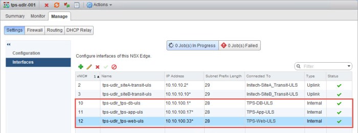
Navigate to the Logical Switches in NSX, click the green plus (+) sign and I create three (3) additional ULS with the following names: TPS-DB-ULS, TPS-App-ULS and TPS-Web-ULS.
Upon completion I now have three new ULS that I will connect to the new ULDR next. Here is a summary of the new ULS.

Connect the ULS to the ULDR
- Next I am going to create three (3) new interfaces on my ULDR. Simply navigate to the Manage > Settings > Interfaces page of your ULDR in the primary site and click the green plus (+) sign.
- In the Edit Logical Router Interface dialog box I provide a name for the interface and then select Internal for Type. Click Change and I select my TPS-DB-ULS which I just created. I then click the green plus (+) sign under Configure Subnets and type the address that I want for this segment. This will become the default gateway for the appliances on this network. I subnetted my networks for this 3-tier appliance and decided to use a /28 mask. Click OK.

- Next I will repeat these steps for my two remaining ULS. Each with a different static IP address.


- Once I am finished I now have three (3) new interfaces (LIFs) added to my ULDR.
Connect VMs to the new ULS
Next I am going to connect my VMs to the new Universal Logical Switches (ULS) and begin testing connectivity. The following VMs have been deployed. Simply repeat the steps in the slideshow below to connect each VM to is respective ULS. The first 3 VMs in the chart below are connected in Site A and the last VM (secondary web server) is connected in Site B.

Begin testing connectivity to your VMs. You want to test functionality from the physical network in each location and attempt to access the resources in each ULS.
- Local control station (Windows 10 system) connected to physical network in Site A. From a command prompt I verify that I can ping each system. I have everything registered in DNS so I ping using the hostname. As you can see I have no problem getting to any of my systems.

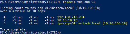
- The ‘tps-web-02’ VM is running in Site B and my control station is in Site A. I want to see the path my control station uses to get to tps-web-02. As you can see from the tracert command output below, my control station used the local ESG in Site A to get to the tps-web-02 VM versus going across the WAN (VPN) link between the two sites.

- Repeat those two tests from your opposite site and you should have the same results. If I were to run a tracert from any system in Site B and to any of the three VMs running in Site A it would utilize the ESG in Site B to get to the VMs (as seen below).
- My last test for now is from my ‘tps-web-01’ VM. I execute a ping to each of the other VMs connected to their respective ULS. Here is the output from that test.

Anther test that you can do to verify local egress is from a web browser. I performed this test from a Windows VM connected to one of the ULS that was created. Use one of your favorite search engines and do a search for “what is my ip address” and watch what comes up. It should be public interface side of your primary external router. This would be the external NAT interface of my pfSense routers that you see in my diagram. I won’t be demonstrating that for you because….well you get it. Security reasons! I don’t want the whole world seeing my organizations public IP address!
I have a different public IP address on each of my pfSense routers. So if I perform this test from Site A I will see Site A’s public NAT address from the ISP. If I perform it from Site B I will see the pubic NAT address from that sites pfSense router. Get it? Good! 🙂
Now go #RunNSX!
Conclusion
So that’s all there is to it for setting up NSX Universal Logical Routers and Switches and utilizing Local Egress. It is a long procedure that requires a lot of planning and extra verification steps. You want to make sure everything is carefully planned out accordingly or you will find yourself trying to undo a lot of steps and it can get very messy.
Remember to RTFM! 🙂 Always saves a headache or two! Lastly check out some of the useful links below.
Useful Links
How Cross-vCenter NSX Works (NSX 6.3 Documentation Center)
NSX Local Egress (NSX 6.3 Documentation Center)
NSX Local Egress (Elver Sena Sosa’s Blog Page – Elver’s Opinion)
VMware NSX for vSphere (Documentation Homepage)
NSX-V: Multi-site Options and Cross-VC Design Guide (NSX Blog by Humair Ahmed)
pfSense (Open Source Virtual Router) – great for configuring routing in a lab environment!

Great write-up! I have installed NSX a couple times but this is the first time I am doing it cross-vCenter. I have a question which I have not been able to find documented yet, when configuring the VXLAN in the secondary site does the VLAN ID need to match that of the VXLAN in the primary site? Thanks in advance for any guidance.
LikeLike
Thank you. You can do that with a stretch L2 technology (if you have it) but it is not required in order to set this up between sites. Just make sure the controllers are able to communicate directly with those VTEPS in the remote site or else you end up with an Agent Down error like I did. The problem I had was a fat fingered static route somewhere in my config.
LikeLike
Thanks for the reply! So you’re saying for stretched layer 2 (which is the goal) the VLAN ID should match across sites? That makes sense. I am assuming the VXLAN MTU size should also match across sites, is the MTU of the VXLAN dependent on the MTU of the physical network or will it be segmented on egress from the ESG? thanks again!
LikeLike
You only need the 1600 MTU for the VXLAN segment which is basically on the physical network. The physical infrastructure is nothing more than your VXLAN backbone. You’re still going to have VLANs and other network segments for out of band management, vMotion, IP based storage, etc. which can also remain on the standard 1500 MTU. The VXLAN segment must be 1600 or greater. The switches that connect to your hosts can be tricky. Some physical switches need to have MTU set at a global level (meaning the entire switch will use Jumbo Frames) and other switches are intelligent enough to set MTU sizes on a per port / per VLAN basis. Most likely find that capability on a high end core switch like a Cisco 6500 Series or Nexus 7K. Bottom line is that 1600 MTU must be set for that VXLAN segment for the VTEPs on each ESXi host. In vSphere you’re going to set the MTU to 1600 or higher on the vDS. And one last tip when changing MTU sizes…make sure the same MTU is set from end-to-end or else you will experience interruptions on the network because it’ll become severely fragmented.
LikeLike
Thanks for sharing, does your pfSense routers also run ospf with UDRL and NSX edge?
LikeLike
I’ve played with multiple configurations just to see how things would play out. I’ve tested it with everything from OSPF, BGP and static routes and sometimes a combination of each with route redistribution. I recently swapped out my pfSense virtual routers with VYOS virtual routers.
LikeLike
Thanks for reply, I setup my lab setup by step from your example. But the VM in siteA and VM in siteB can’t ping each other. VM in siteA can ping 192.168.100.1, and VM in siteB can ping 192.168.100.2.
Site A and Site B doesn’t exchange routing in my lab. Is this the problem siteA VM can’t ping SiteB VM?
LikeLike
Definitely have some sort of routing issue. Also double check and make sure your VTEP vmkernel’s can PING between the two sites.
Example from ESXi host:
ping ++netstack=vxlan -I vmk3 192.168.110.31
The vmkernel interface I’m using above is the vmkernel of the hosts VTEP. The target IP is a remote ESXi hosts VTEP IP address.
LikeLiked by 1 person
Thanks for reply, Now VTEP vmkernel’s can PING between the two sites. VM from site A,B can ping each other, but it’s only one hop to get each other. VM don’t through ESG to another site. I have check the routing, It works well now. The locale ID have been set, switch MTU also changed to 1600. It’s really don’t know where the problem is..
LikeLiked by 1 person
I just let Site A and Site B can exchange routing. But the VM in siteA and VM in siteB still can’t ping each other. I think it’s the problem I don’t change MTU in switch.
LikeLike
Double check all of your settings….MTU, routing tables, etc. because something is likely off.
LikeLiked by 1 person
I have a similar setup. Everything is working as expected, except that when I try to SSH to a VM on site B which is on the same segment “across the UDLR” from a VM on site A, I cant reach it. But, interestingly enough I can ping between both of them. Firewall is not blocking any traffic and I have done couple of trace-flow operations and all came back with the result “Delivered” any idea what might be causing this?
Thanks much!
LikeLike
This blog post is very informative about setting up Multi-Site NSX.
LikeLike