I have had nothing but fun working with NSX over the past few years. I love everything about it from design, deployment to managing it. Such a fantastic solution that brings a LOT to the table including deploying logical networks in just a few clicks to enhanced security thanks to microsegmentation. This post is for you folks out there seeking for that more in-depth look of what is going on behind the scenes between virtual machines when they communicate with one another with NSX. I also feel every NSX admin should have a firm grasp on the architecture and understand how to troubleshoot issues. I compare this to knowing how to do math on pen and paper versus using a calculator.
We are going focus capturing packets as they traverse the NSX network and get a clearer picture of what is going on in the background.
- What does the packet path (data path) look like when a VM communicates with another VM on the same logical switch (network segment) between ESXi hosts?
- What does the packet path look like when VMs communicate between different logical switches?
Many different scenarios and we are going to cover just a few here in this logical switch packet walk and get you familiar with the process of capturing and examining this information.
First thing we need to do is gather some key info about the VMs, ESXi hosts, logical switches and so on..specifically IP addresses and MAC addresses. We are going to walk through this process using the vSphere Web Client and record the information. I like to set up a spreadsheet to help me with this. There is an easier way of accomplishing this using RV Tools (FREE) which you can quickly export your entire vSphere environment into one big spreadsheet. But for educational purposes I’m going to show you where to locate this information in the vSphere Web Client. Too much unnecessary hatred and animosity towards the vSphere Web Client.
If you are really good at PowerCLI you could probably use that as well :).
Gather Information
So I created a nice and simple spreadsheet to record some information I want to collect from my environment. I created two separate tables…one is for my virtual machines and the other is for my ESXi hosts. We will start with the virtual machines which are all connected to a logical switch based on the 3-Tier application that I have deployed. Below is a logical diagram of the environment that I will be working with.

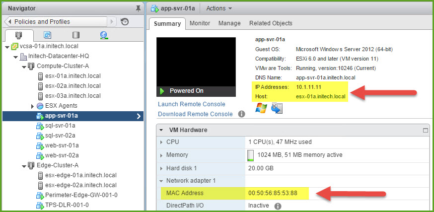
Connect to the vSphere Web Client and then open Hosts & Clusters and begin collecting information about our VMs first and then our hosts. I have five (5) VMs in my Compute Cluster where I will collect the IP Address and MAC Address of each. Simply choose one of the VMs and then select the Summary tab. At the very top you ushould see the IP Address(es) associated with this VM. Record that in your spreadsheet. Next expand Network adapter 1 under VM Hardware. There you will find the MAC Address for this VM. Record that in your spreadsheet. And lastly record which ESXi host your VM is running on.
Repeat this process for each of the VMs in your compute cluster that you want to use during your packet capture. The screenshot below displays the information I gathered from my ‘app-svr-01a’ virtual machine.
The next thing we need is the Port ID for each VM on the distributed switch. So I simply connect to each ESXi host in my cluster (3 hosts) and then enter the esxtop command and then press ‘n’ to view the network information. Locate the VM and in the first column (far left) is the ‘PORT-ID’ column. Record the PORT-ID for the virtual machine. Repeat this step on each host until you have the PORT-ID for each of your VMs.
Here is my table containing the information I need for my virtual machines that I want use in this packet walk exercise.

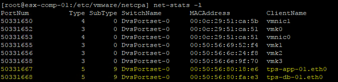
Another method to find the VM Port-ID, a much easier one, would be to execute the netstats -l command from an ESXi host. Doesn’t get much easier than that! Now you know the long way and short way.
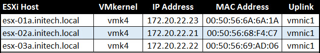
Next I need to gather some information about my ESXi hosts. Specifically the IP Address and MAC Address of the VMkernel adapter associated with the VTEP (VXLAN) on each host.
From the Hosts & Clusters console, select an ESXi host and then select the Manage tab. Then select Networking and then choose VMkernel adapters. The VMkernel associated with the VTEP is easily identifiable by ‘vxlan’ in the TCP/IP stack column. Select the VMkernel and below you will see not only the IPv4 address but the MAC address. Scroll down a little bit under the All tab until you see Teaming and failover. Here you will find the ‘Active uplinks’ and the ‘Standby uplinks’…record the Active uplink for the host.
(NOTE: If it just says ‘Uplink 1’ or ‘Uplink 2’ you may have to go into your vDS configuration because you want the specific vmnic associated with that vDS uplink.)
Repeat these steps on each of the ESXi hosts and enter them into a separate table in your spreadsheet.
NSX Packet Capture Introduction
In this task we are going to capture packets between two virtual machines running on the same NSX logical switch operating on the same ESXi host. If you have been working with vSphere you probably already know what the end result is going to be. My main goal with the introduction here is to only familiarize you with command-line tools used to capture and analyze. So simple and high-level here 🙂 . I am going to begin with the following virtual machines running on the same ESXi host:
- web-svr-01a
- IP Address: 10.1.13.11
- MAC Address: 00:50:56:85:B7:5B
- Port ID: 67108884
- web-svr-02a
- IP Address: 10.1.13.12
- MAC Address: 00:50:56:85:0B:31
- Port ID: 67108883
- esx-03a
- IP Address: 172.20.22.22
- MAC Address: 00:50:56:69:AD:06
This information is critical to our packet capturing process across NSX. The next thing we are going to do is initiate a continuous PING from web-svr-01a to web-svr-02a. Once that is running I am going to open a Putty (SSH) session with esx-03a and execute the following command to begin the packet capture:
pktcap-uw -o /cap/web-svr-01a.pcap --switchport 67108884 --dir 0
Before we go further let’s dissect this command a little bit. First the ‘-o’ parameter is used to specify an output file. I created a new directory on my ESXi host (/cap) to use for my packet capture files. I am dumping the packet capture to a file with the ‘pcap’ file extension into the /cap directory. This ‘pcap’ file can be SCP’d to an admins desktop and viewed in Wireshark or other type of utility.
The ‘–switchport’ parameter is used because we want to capture packets from a specific VM based on the port ID being used on the virtual switch. Inbound or outbound is determined by the ‘–dir’ parameter according to the vDS. A value of ‘0’ is used for observing traffic inbound (Rx) to the virtual switch; a value of ‘1’ is used for observing traffic outbound (Tx) the virtual switch.
NOTE: The pktcap-uw tool was introduced in ESXi 5.5 and is included by default. To view additional parameters and/or options for the packet capture command type the command ‘pktcap-uw –help’.
Once you have executed the packet capture let it run for about 10 seconds. Press CTRL+C to stop the capture. Next we want to view the contents of the packet capture. To do this we are going to use the ‘tcpdump-uw’ utility to enumerate the output file that was just created. Type the following command to display the contents of the output file:
tcpdump-uw -enr /cap/web-svr-01a.pcap
The contents of the capture file will then appear. If you are familiar with packet captures then locating the information will be very simple. If you are new to viewing this information, don’t worry…its pretty simple.
First thing you are going to see (from left to right) is a timestamp. Next you are going to see ‘Source MAC’ > ‘Destination MAC’. You will then see some other information including ethertype (IPv4, ARP, etc.), packet length until you get to some IP addresses. Same thing applies here….’Source IP’ > ‘Destination IP’ followed by additional information. We initiated a continuous PING so I am specifically looking for ‘ICMP echo request’ entries.
Here is the output from my continuous PING from web-svr-01a to web-svr-02a. I have truncated some of the information to make it viewable. I’ve also included the screenshot in case you have superman’s eyesight 🙂
00:50:56:85:b7:5b > 00:50:56:85:0b:31...10.1.13.11 > 10.1.13.12: ICMP echo request...

As you can see here this is as direct as you can get with communication. Two VMs communicating with each other on the same network segment. VMs don’t even have to be on a logical switch to do this. The traffic were captured is not encapsulated by NSX (VXLAN). Very basic procedure that any vSphere admin should be able to accomplish. You don’t even need NSX installed to accomplish this simple task above. I simply want to get you familiar with a couple commands that we are going to use here shortly.
Now lets take a look at some more complex packet captures that will allow us to view a packet that has been encapsulated by NSX.
NSX Packet Capture Task 1
The previous task was nothing more than to get your familiar with packet capturing and viewing this info directly from the ESXi host. Good little process for some of you who may be new to NSX. Now we are going to change it up a bit and start looking at actual traffic being encapsulated and un-uncapsulated by NSX. We will view some critical VXLAN information including the VNI of our NSX logical switches.
The next packet capture we are going to do is look at what happens when two VMs on the same NSX logical switch communicate with one another and operate on separate ESXi hosts. Pretty simple.
First we are going to work with the two SQL virtual machines that I have running (reference table above). The VMs are both connected to the TPS-DB-Tier-LS with the segment ID of 5002 (or VNI 5002). I started a continuous PING from sql-svr-01a to sql-svr-02a. Here is a quick summary of what we will be working with.
- sql-svr-01a
- IP Address: 10.1.12.11
- MAC Address: 00:50:56:85:A5:6B
- Port ID: 67108877
- Host: esx-02a.initech.local
- sql-svr-02a
- IP Address: 10.1.12.12
- MAC Address: 00:50:56:85:17:A4
- Port ID: 67108885
- Host: esx-03a.initech.local
- esx-02a.initech.local (VTEP VMkernel info)
- IP Address: 172.20.22.21
- MAC Address: 00:50:56:68:F4:C7
- Uplink: vmnic1
- esx-03a.initech.local (VTEP VMkernel info)
- IP Address: 172.20.22.22
- MAC Address: 00:50:56:69:AD:06
- Uplink: vmnic1
The source VM (sql-svr-01a) that I want to capture is running on esx-02a.initech.local. The continuous ping is already running so I’m ready to go. I then open an SSH session with that host and execute the following command.
pktcap-uw -o /cap/sql-svr-01a.pcap --switchport 67108877 --dir 0
Here I am capturing the inbound traffic (Rx) on the virtual switch. Allow the packet capture to run for about 10 seconds and stopp it with CTRL+C. Next we are going to observe the contents of the packet capture and type the following command:
tcpdump-uw -enr /cap/sql-svr-01a.pcap
Immediately I can see the ‘Source MAC > Destination MAC’ followed by the ‘Source IP > Destination IP’ and the ICMP Echo request. Look for the initial ARP request too!

I apologize for the small screenshot but the ARP request states in the output above:
Request who-has 10.1.12.12 (00:50:56:85:17:a) tell 10.1.12.11
Now here is a snippet of the actual ICMP echo request from sql-svr-01a to sql-svr-02a.

Next we are going to execute another packet capture on the same host (source ESXi host) except we are going to execute this capture on the active ESXi VTEP uplink (vmnic) specifically the outbound (Tx) traffic. To do so I execute the following command and include the ‘stage’ parameter:
pktcap-uw -o /cap/sql-unencap.pcap --uplink vmnic1 --dir 1 --stage 0
The ‘stage’ parameter has two possible values. A value of ‘0’ is for before (pre) and a value of ‘1’ is for after (post).
Comb through the content and you will find the ICMP echo request. We are looking for the pre-staged outbound (Tx) packet. You should see the Source MAC > Destination MAC followed by the Source IP > Destination IP just as we did before. The packet has not been encapsulated by VXLAN at this point.

Execute the following command to view the packet LEAVING the virtual switch as an encapsulated frame by modifying the value of the ‘stage’ parameter:
pktcap-uw -o /cap/sql-encap.pcap --uplink vmnic1 --dir 1 --stage 1
Here is a screenshot of the packet capture.

Immediately you are going to see the ‘Source MAC > Destination MAC’ except this time it is the MAC addresses of the VTEP listed first. You also see the IP addresses of the VTEPs communicating and lastly the VXLAN, VNI 5002 is also present. This is the ENCAPSULATED packet!
Task 1 Summary
We have two VMs on the same NSX logical network segment running on separate ESXi hosts. Communication will involve the VTEP VMkernel’s on the source and destination hosts to handle the transmission.
We were able to see the VTEP on esx-02a (172.20.22.21) communicating with the VTEP on esx-03a (172.20.22.22). The original packet is encapsulated by NSX (VXLAN) and transmitted.
NSX Packet Capture Task 2
Here in the final packet capture task we are going to initiate communication between two VMs connected to separate NSX logical switches and on separate hosts. The NSX logical switches are all connected to the same DLR (Distributed Logical Router) as seen in the diagram above. Will the DLR play a role in this transmission? Let’s find out.
So we are starting with two VMs on separate logical switches on different ESXi hosts. I reference my VM table above and see that sql-svr-01a and web-svr-01a fit this criteria. I initiate a continuous PING from sql-svr-01a (10.1.12.11) to web-svr-01a (10.1.13.11). Here is a quick summary of what we will be working with.
- sql-svr-01a
- IP Address: 10.1.12.11
- MAC Address: 00:50:56:85:A5:6B
- Port ID: 67108877
- Host: esx-02a.initech.local
- NSX Logical Switch VNI: 5002
- web-svr-01a
- IP Address: 10.1.13.11
- MAC Address: 00:50:56:85:B7:5B
- Port ID: 67108884
- Host: esx-03a.initech.local
- NSX Logical Switch VNI: 5003
- esx-02a.initech.local (VTEP VMkernel info)
- IP Address: 172.20.22.21
- MAC Address: 00:50:56:68:F4:C7
- Uplink: vmnic1
- esx-03a.initech.local (VTEP VMkernel info)
- IP Address: 172.20.22.22
- MAC Address: 00:50:56:69:AD:06
- Uplink: vmnic1
We will execute two packet capture commands; one to capture the packet coming from sql-svr-01a into the virtual switch and a second command to capture the packet leaving the virtual switch for web-svr-01a.
The 1st packet capture for svr-svr-01a will be executed on esx-02a:
pktcap-uw -o /cap/sql-svr-01a.pcap --switchport 67108877 --dir 0
The 2nd packet capture for web-svr-01a will be executed on esx-03a:
pktcap-uw -o /cap/web-svr-01a.pcap --switchport 67108884 --dir 1
I allow them to run for 10 seconds and then enumerate them using the ‘tcpdump-uw’ command. First let’s examine the packet capture on esx-02a as it leaves the sql-svr-01a VM destined for web-svr-01a.
tcpdump-uw -enr /cap/sql-svr-01a.pcap
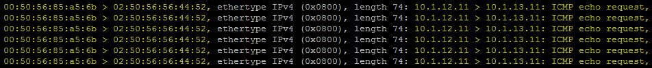
You may already notice but the Layer 2 information in this packet is much different than what we viewed in the first packet capture task. The Source MAC address is from the sql-svr-01a virtual machine but the Destination MAC (02:50:56:56:44:52) is nothing in my table above or in any of my recorded information. So where did this MAC address come from? If you said the DLR you are correct!
Let’s examine the packet capture on esx-03a and see what that looks like.
tcpdump-uw -enr /cap/web-svr-01a.pcap
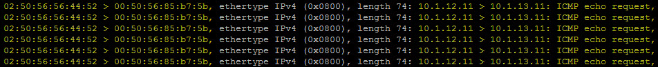
Look at the Source and Destination MAC addresses above. Notice the Source MAC Address here is the same as the Destination MAC Address in the capture we just examined on esx-02a.
Before going any further….how can I find the MAC address (02:50:56:56:44:52) associated with my DLR? Very Simple. First you want to putty (SSH) into your NSX Manager and then execute the following command to obtain the VDR name of the DLR:
show logical-router list all

The name of my DLR is ‘Initech+edge-2’. I then return to my SSH session on my ESXi host and type the following command:
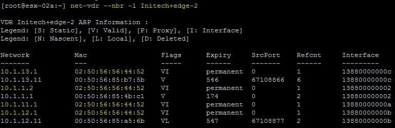
net-vdr --nbr -l Initech+edge-2
The MAC address we are looking for is ’02:50:56:56:44:52′ and as you see it appears four (4) times in the output below. This MAC address is generated when the DLR uplink interface is created and then applied to any of the Internal Interfaces that connect to the NSX logical switches.
Now lets take a look at the packet as it is encapsulated by NSX. First we are going to execute the following command on the source host esx-02a:
pktcap-uw -o /cap/sql-svr-unencap.pcap --uplink vmnic1 --dir 1 --stage 0
Allow the command to run for about 10 seconds again and then examine the packet capture.
tcpdump -uw -enr /cap/sql-svr-unencap.pcap
We are capturing the packet at the ‘vmnic’ on the host and not the ‘switchport’ which is associated with the VM. So our Source and Destination MAC addresses at vmnic will look like this:

The Source MAC will be from the DLR and the Destination MAC will be the MAC of web-svr-01a. The Layer 3 information (Source IP to Destination IP) will have the IP addresses of sql-svr-01a and web-svr-01a as expected.
Now let’s look at the encapsulated packet by executing the following packet capture on the destination host (esx-03a):
pktcap-uw -o /cap/web-svr-encap.pcap --uplink vmnic1 --dir 1 --stage 1
I allow the capture to run for about 10 seconds and then examine the packet capture.
tcpdump -enr /cap/web-svr-encap.pcap

And there is my VXLAN encapsulated packet. You will see the Source MAC and Destination MAC of the ESXi host VTEP VMkernel adapters. This time around we are seeing the ‘ICMP echo reply’ instead of the request. You will also see ‘VXLAN, VNI 5002’ in the capture which is the VNI for sql-svr-01a which is connected to the DB Tier Logical Switch in my NSX environment. The ICMP echo reply is destined for this segment.
Packet Capture Summary
So there you have it. The tools and the procedure that can be used by an NSX admin to capture and view traffic as it traverses the NSX overlay. I believe every NSX admin should know and understand this procedure regardless of any other management & monitoring tools that may have at their disposal. It will really help enhance your knowledge and understanding NSX so when you finally move forward and implement vRealize Network Insight (vRNI), vRealize Operations Manager and/or vRealize Log Insight you will know what to expect from those incredibly useful tools.
Like I stated in my math analogy earlier. Knowing how to do things “long hand” versus relying on a tool to do everything for you will always give you an advantage in my opinion.
So this concludes my NSX Logical Switch Packet Walk post. I will have two more ‘Packet Walk’ posts coming for you in the future including:
- DLR (Distributed Logical Router) Packet Walk
- DFW (Distributed Firewall) Packet Walk
Looking forward to both, especially the DFW packet walk as we will see traffic that is permitted and not permitted in our packet captures!
So stayed tuned and remember…
BE SOCIALABLE & SHARE! 🙂

wow, very nice. I never saw this much nice explanation. I really thankful for sharing this type if core and deep information from packet level capturing and analysis. Very nice.
LikeLike