In my previous blog article I covered single-tier routing in NSX-T whereby a single T0 gateway was deployed and provided network connectivity for my virtual workloads. This T0 gateway provided both N-S and E-W traffic flows. In this article I am going to cover Two-Tier (multi-tier) routing; this topology creates a logical separation between provider and tenant functions and ideal for multi-tenancy.
With two-tier routing, you will find both T0 and T1 gateways (virtual routers). The T0 gateway is common referred to as the ‘provider’ and the T1 would be the ‘tenant’. This design enables provider admins and tenant admins total control over their services and policies because they operate separately from one another.
Next let’s discuss a little about traffic flow. The T0 gateway handles all northbound traffic and can connect with one or more physical routers and/or L3 switches. Southbound T0 traffic traverses something called a ‘RouterLink interface’ which established between the T0 and T1 gateways. The T1 gateway has northbound connectivity to the T0 gateway through this interface and then southbound interface(s) are called ‘downlinks’ which are from the T1 gateway to one or more L2 segments. T1 routers cannot connect directly to the physical underlying infrastructure, only T0 routers can provide connectivity to the physical network commonly referred to as the underlay.
The concepts of distributed routers (DR) and service routers (SR) are no different than what we saw in my previous blog article with single-tier routing. One area that is different in this topology compared to single-tier is the use of the RouterLink Interface (Linked Port) which is used to connect T0 and T1 gateways as I just mentioned a moment ago. A peer connection is established using the 100.64.0.0/16 reserved address space (RFC 6598). It will appear in the configuration as a /31 subnet which you may see during the step-by-step exercise when establishing the connectivity between T0 and T1.
This connectivity is entirely ‘auto-plummed’ into the configuration and therefore no dynamic routing is required between T0 and T1. Previously in NSX-V, admins would create a logical switch that would function as a ‘transit network’ between the ESG and DLR and dynamic routing would be configured between the two (OSPF, BGP or static routes). That logical switch that functioned as a transit network between the two layers in NSX-V is no longer needed in NSX-T.
You can read more about T0 and T1 connectivity, route types, route advertisements and so on in the NSX-T Reference Design Guide; two-tier routing begins on Page 53. I highly recommend reading this document from start to finish several times. It is a well written document and will really help you solidify your understand of not only NSX-T routing concepts but the entire platform as a whole.
In this blog article I’m going to deploy a single T0 gateway, a single T1 gateway and then connect the two. Once the gateways are deployed I will then deploy a 3-tier application with each layer connecting to corresponding L2 network segment which will then connect directly to my T1 router. Reference the logical diagram below; Web, App and DB are the Segments that will be created.

Step-by-Step Two-Tier Routing Procedure
The following procedure is being done using NSX-T 2.5.1 (Build 2.5.1.0.0.15314292). The release notes for this specific version can be found in the Useful Links section at the bottom of this blog article.
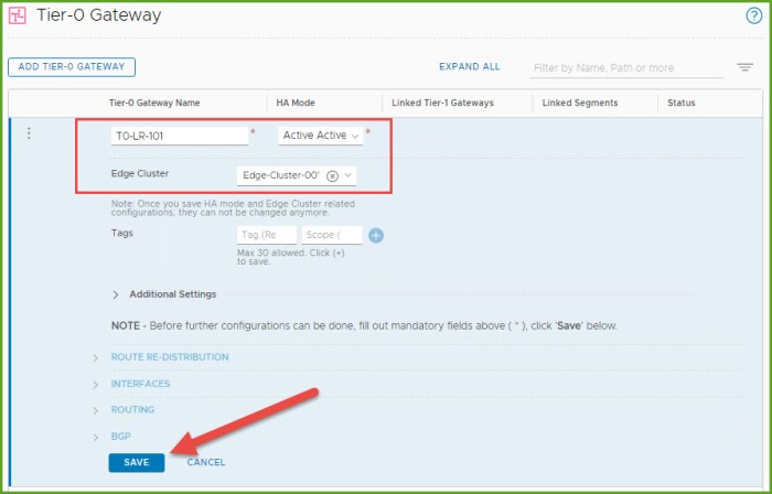
- Log into NSX-T Manager and navigate to Networking, Tier-0 Gateways under Connectivity and then click the ‘Add Tier-0 Gateway’ button.

- Provide the T0 gateway with a name and select the Edge Cluster. Click Save. When prompted to continue configuring the Tier-0 gateway select No. Verify the T0 appears in the inventory and status is UP.
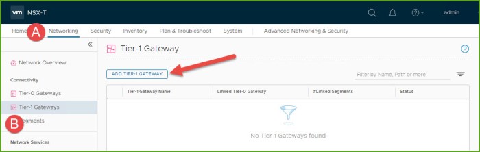
- Select Tier-1 Gateways under the connectivity section on the left and then select the Add Tier-1 Gateway button.
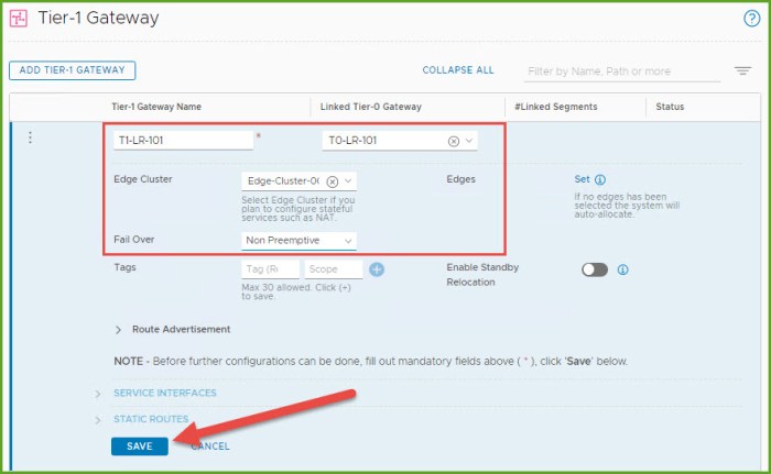
- Provide the Tier-1 gateway with a name, select the new T0 gateway that was just deployed, select the Edge Cluster and click Save. When prompted to continue configuring the Tier-1 gateway select No. Verify the gateway in the inventory and status is UP. The ‘RouterLink’ interface between the T0 and T1 logical routers will be established dynamically behind the scenes.
- Navigate back to the T0 router that was created and from the options menu select Edit.

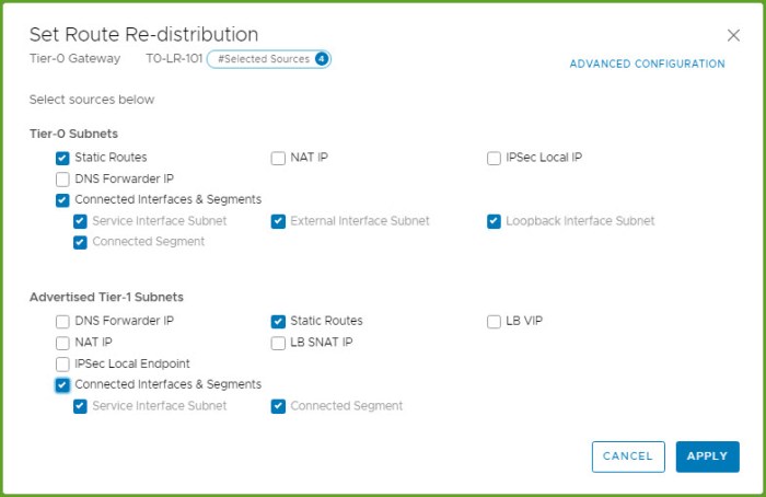
- Expand Route Re-Distribution and click Set. Select the following for Tier-0 Subnets and Advertised Tier-1 Subnets. Click Apply and Save.
- Expand Interfaces and click Set. From the Set Interfaces dialog box, click on the Add Interface button. Here we are going to create the uplink interface that communicates with the physical network. Provide a name for the interface, select External for the type, provide an available static IP, choose the external uplink segment (created this segment in my Single-Tier Routing blog article), select and Edge Node from the drop-down menu and click Save and then Close.

- Expand BGP and enter the local AS and then next to BGP Neighbors select Set.
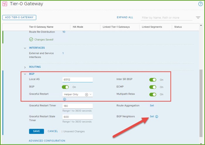
- The Set BGP Neighbors dialog box appears. Click on the ‘Add BGP Neighbor’ button. Enter the IP address and Remote AS for the BGP peer. Click Save and then Close. Refresh the Status until it says UP (assuming you have properly configured BGP on the remote router).

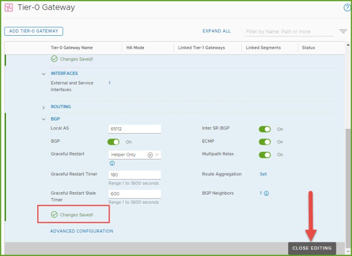
- Back at the main screen for the T0 gateway, select Save beneath BGP and then select Close Editing.
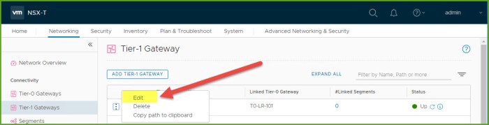
- Navigate to the T1 Gateway that we provisioned earlier and from the Options menu select Edit.
- Enable the options for ‘All Static Routes’ and ‘All Connected Segments & Service Ports’ and then click Save and lastly Close Editing.

- Next we are going to create the three (3) segments for our 3-tier application: Web, App and DB segments. Navigate to Segments and click the Add Segment button.

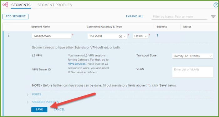
- Enter a name for the segment, select the new T1 gateway that was just provisioned, verify the Overlay TZ is selected and then select ‘Set Subnets’.
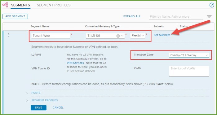
- The Set Subnets dialog box appears, click the ‘Add Subnet’ button. I then enter the gateway IP for my new intended Web segment. Click Add and then Apply.
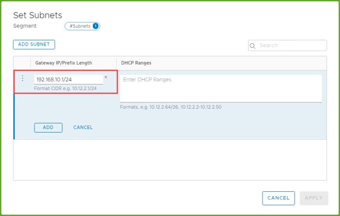
- Back at the Add Segment window, click Save. When prompted to continue configuring the segment click No.
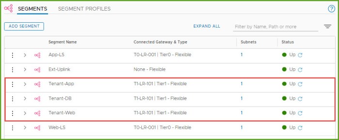
- I then repeat Steps 13-16 and create my remaining two segments for my 3-tier application. When I am finished all three segments will now be connected to my new T1 gateway.
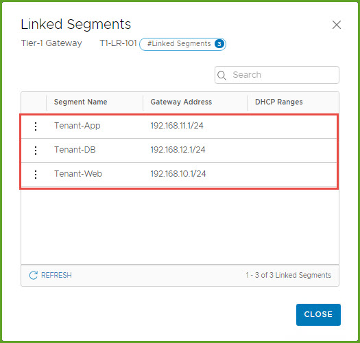
- Before I started this exercise, I provisioned the VMs for this exercise. Now that the segments are created I can now go back and connect the VMs to their respective NSX-T network segments. You can verify the segments are connected to the T1 gateway by select the # under the Linked Segments column for your new T1.
- Navigate to the segments that were just created and expand the segment and then expand Ports. Select the # next to ports
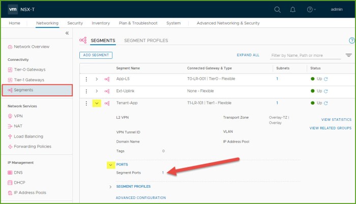
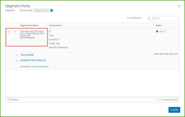
- In the ‘Segment Ports’ dialog box, examine the details for the port name. As you can see below my virtual machine is associated to the following port on the segment. Click Close when finished.
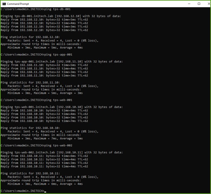
- From a command-line, test connectivity to the VMs that are now connected to the new segments. As you can see below I can connect to these four (4) workloads from my workstation which is connected to my underlay. Therefore this validates that I have connectivity from my ‘underlay -> T0 GW -> T1 GW -> Segments’ in my NSX-T environment.
Two-Tier Routing Summary
The fully distributed routing architecture of NSX-T is intended to provide routing functionality closest to the source; capable of extending it to multiple tiers. NSX-T supports both static routing as well as dynamic routing through the use of BGP on the T0 gateways. The T1 gateways support static routes but do not support any dynamic routing capabilities. This is were effective NSX-T Route Redistribution will come into play.
If you are not familiar with BGP then I highly recommend reading up on it as it is the ‘de facto standard’ protocol when it comes to WAN connectivity. Typical spine-leaf architectures use eBGP between the spine switches and and leaf switches.
iBGP means the adjacent BGP routers that are being configured as neighbors share the same ‘Autonomous System (AS)’ number. If the AS is different between the two then eBGP is being configured. iBGP has the following capabilities and limitations:
- Redistribution, route-maps and prefix lists are all supported.
- BGP confederation and route reflectors are not supported.
When eBGP is being configured the neighbors must be connected directly to the same network segment (subnet) as the tier-0 uplink. If they are not in the same subnet then BGP multi-hop must be used.
Want to learn about NSX-T Single-Tier Routing? Check out my other blog article!
Useful Links
NSX-T Reference Design Guide 2.0 (PDF) – for versions 2.0 – 2.5
VMware NSX-T Data Center Documentation
VMware NSX Training and Demos (YouTube Channel)
VMware NSX-T 2.5 Release Notes
VMware NSX-T 2.5.1 Release Notes

2 thoughts on “NSX-T Two-Tier Routing”