Here I am going to show you how to enable the “basic” vCenter HA option across multiple clusters. Why do this across multiple clusters? Easy…increase the availability of my vCenter HA instance. Could I enable this in a single cluster if I had to? Sure. If you are limited to a single cluster and want to still use vCenter HA you can certainly do so. Better to have it than not have it right? You simply have the risk of losing the entire cluster and your entire vCenter HA instance is down anyway. But if that happens you likely have bigger issues to be concerned about and vCenter HA isn’t going to rescue in that situation. You should probably have some sort of mutli-cluster or multi-site configuration instead.
Anyway…I’m getting off topic a little bit.
I decided to write this blog article because I have come across this process for a customer recently. The vCenter HA instances I have enabled previously have all been of the “Advanced” flavor and used a separate load balancer. I have finally come across a customer that simply wanted to do this using the “Basic” option and their new vCenter Server appliance is also configured with an embedded PSC. Enabling this is very, very easy to do.
First, let’s review how I have this “labbed” up environment configured. I have two (2) ESXi hosts running vSphere 6.5 U1 and my vCenter Server appliance (VCSA) is deployed with an embedded PSC. Static IP addressing will be important here so make note of the static IP addresses that you will be using. There will be a separate vCenter HA network that will be used here that is completely separate from the Management network.
When vCenter HA is enabled a cloning process will be kicked off and a secondary vCenter Server appliance will be created. This secondary is often referred to as the vCenter HA “peer” appliance. This appliance will completely mimic the primary. The only difference between the primary and peer will be the vCenter HA network adapter static IP address.
A witness appliance is also created during the procedure. This is generated by cloning the vCenter Server and then reconfigured with 1 vCPU and 1 GB of memory. It doesn’t need much to do its job. It is also only connected to the vCenter HA network. It has zero network connectivity with the management network used by my vCenter Server appliances and my ESXi hosts.
Here is a summary of the environment that I will be working with along with the “planned” parameters that I will be using.
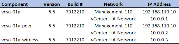
The “peer” and “witness” appliances will be created during the enabling of vCenter HA and not cloned prior to the procedure that I am going to take. This information above is simply for planning and verification purposes.
My vSphere environment is very simple for this procedure. I have two clusters with a single ESXi host in each. In a real world situation I would obviously have more here but for demonstration purposes this is all I will need to enable and use vCenter HA.
- Cluster-A contains ESXi host esx-101.initech.local which is configured with a management IP address of 192.168.110.101.
- Cluster-B contains ESXi host esx-201.initech.local which is configured with a management IP address of 192.168.110.201.
I also have a distributed switch deployed for this environment. Aside from my Management network I have the following networks created.
- Management-110 for the 192.168.110.0 /24 network.
- iSCSI-111 for the 192.168.111.0 /24 network and storage access.
- vMotion-120 for the 192.168.120.0 /24 network and vMotion.
- vCenter-HA-Network will be the 10.0.0.0 /24 network.
The vCenter-HA-Network is a network we will have some enhanced focus on during the procedure; I will be using the private 10.0.0.0 /24 network range for this particular network. You can use whatever network range you want. Just be sure it is separate from the primary management network that you use. It can be routable or non-routable on your infrastructure. It’s entirely up to you.
So I have pretty much everything I need ready to go and now I am ready to enable vCenter HA. My existing vCenter Server (VCSA appliance) has already been deployed onto esx-101.initech.local located in Cluster-A. My goals for this are simple:
- Deploy the vCenter HA “peer” VM onto esx-201.initech.local in Cluster-B.
- Deploy the vCenter HA “witness” VM onto esx-201.initech.local in Cluster B.
- NOTE: Enabling vCenter HA will clone everything for me.
I could deploy the witness appliance in Cluster-A or B in this situation or 3rd cluster environment if I had it. I have limited resources at the moment. Per Best Practices for VCHA, the nodes should all be in separate failure domains.
My ultimate goal here for my small lag is get the active and passive nodes running in separate clusters. Let’s get started with enabling Basic vCenter HA.
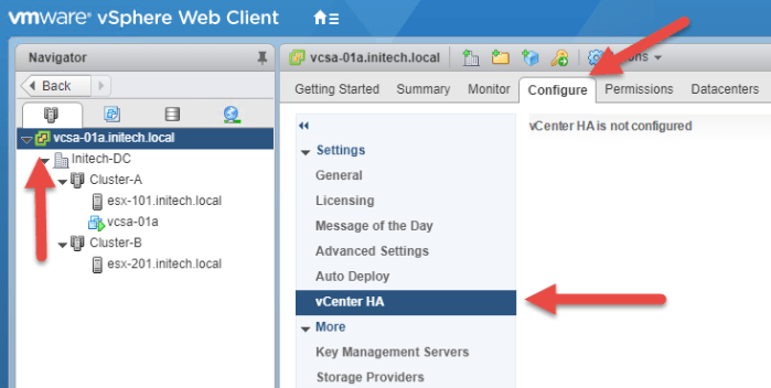
- Log into the vSphere Web Client and then select the name of the vCenter Server (FQDN) at the top of the Hosts and Clusters inventory. Then select the Configure tab and finally select vCenter HA.
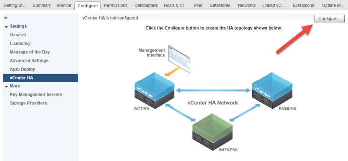
- In the upper right-hand corner select the Configure button. The Configure vCenter HA wizard will appear.
- On the ‘Select a configuration’ option page select Basic and click Next. Notice the only prerequisite here is to have the vCenter HA Network created before proceeding. I have my network on a distributed switch but you can also use a standard switch. All depends on your licensed version of vSphere and what currently use for virtual network connectivity. (Just to be clear…licensing will determine whether or not you can use the vDS and not vCenter HA.)

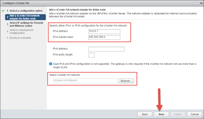
- Next I am going to configure the HA Network settings for my ‘active’ vCenter Server node. This is my existing vCenter Server. This will create a new vNIC on my existing VCSA and connect it to the vCenter HA Network that I previously created. Supply the network addresses that you have reserved for this node and then click ‘Browse’ and select the HA network. Click Next when finished. (Reference my table above)
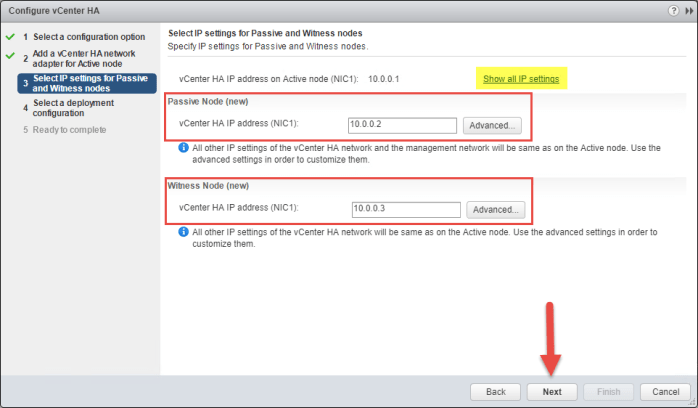
- Next we will configure the vCenter HA network settings that will be used by the Passive Node (aka peer node) and the Witness Node. You can click the ‘Advanced’ buttons next to each option if you need to specify/modify different network parameters such as mask or gateway. The ‘Show all IP settings’ link at the top of the page will display your Active Node TCP/IP settings if you need to quickly reference them without having to click back. In my screenshot you will see the addresses that I entered (reference my table above) and click Next when ready.
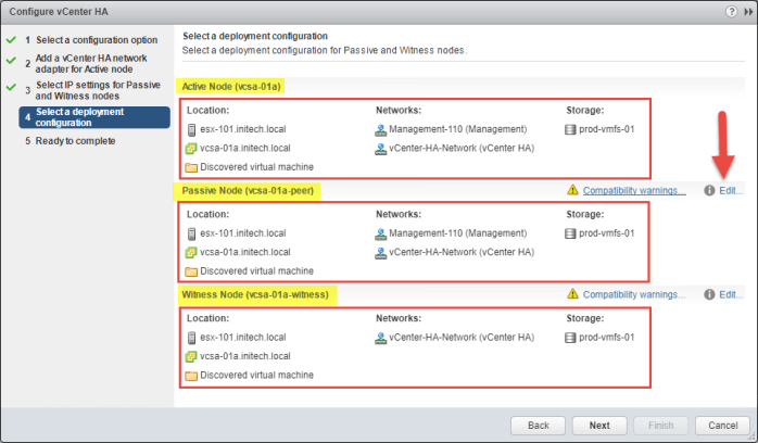
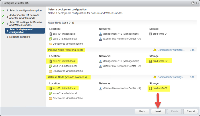
- On the ‘Select a deployment configuration’ page of the wizard is where I want to customize the location of my virtual appliances and where I want them to reside in the ‘multi-cluster’ inventory. My goals were to place the peer and witness nodes into Cluster-B and also use the VMFS datastore that I have configured there. Notice the warnings by default. These warnings are specifically telling me that all of my nodes will reside in the same datastore and there is basically “risk” involved with keeping this conguration. Click the Edit option next to the Passive Node.
- In the new screen select the name and folder location for your “peer” node and click Next. By default the ‘-peer’ suffix is used but you can change it if you want.

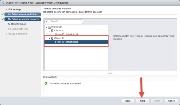
- On the Select a compute resource page I will choose my ‘esx-201.initech.local’ host in Cluster-B and then click Next. This will make sure my peer node will run in Cluster-B and not in the same cluster (Cluster-A) as my primary (active node) vCenter appliance.
- On the Select storage page I will choose a virtual disk format and then select my datastore. In my lab I always thin provision but in your production environment you will probably use some form of thick provisioning. You can also simply leave the option ‘Same format as source’ if you want. Click Next.

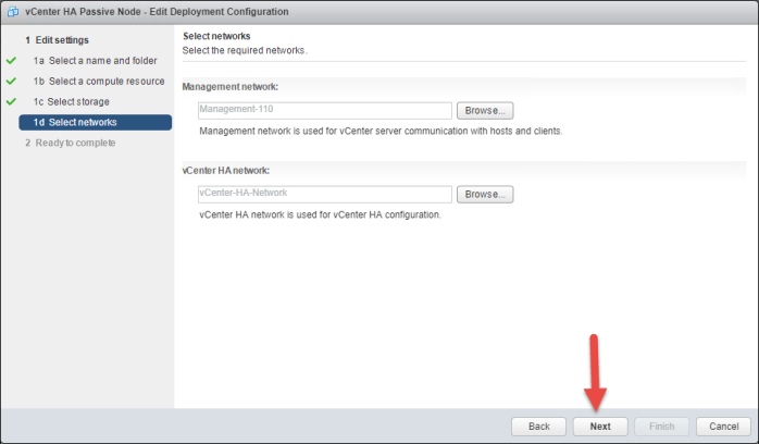
- On the Select network page I’m simply going to review my network selections. Everything looks to be in line with what I want so I’m just going to click Next.
- Review the information and click Finish.
- The original wizard will appear. Click Edit to make changes to the Witness Node and follow Steps 7 – 11 for the Witness node. In a real world situation all three (3) of my vCenter HA virtual appliances (Active, Passive and Witness) I would place on separate datastores (VMFS or NFS). Notice the changes I have made for my Passive and Witness Nodes compared to what we saw in Step 6. Click Next.
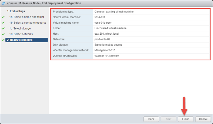
- On the Ready to complete page review the settings for the Passive and Witness nodes by clicking the links to the right and click Finish when ready.

- Follow the Tasks that will appear in the bottom pane. You will quickly see a task complete where the primary VCSA vCenter Server will be reconfigured. This is simply the vNic adapter being added to the appliance for the vCenter HA network. Then a clone procedure will begin to create the “peer” vCenter appliance and then the “witness” appliance. Once the clone procedure completes the appliances will be automatically powered on.
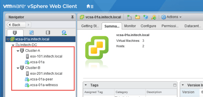
- You can monitor the entire procedure from the Recent Tasks view while vCenter HA is being deployed. My inventory looks like this between my two clusters once everything has been cloned and powered on.
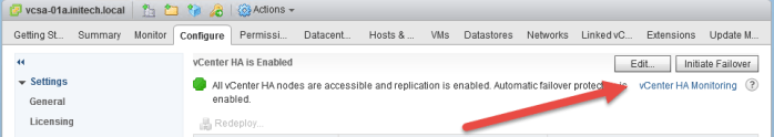
- Once the process finishes you will see vCenter HA is Enabled at the top along with a summary of each HA node. As you can see below there are 3 columns: Role, Status and vCenter HA IP Address. You can see additional parameters for each node below by clicking the IP Settings or the VM Settings tab.
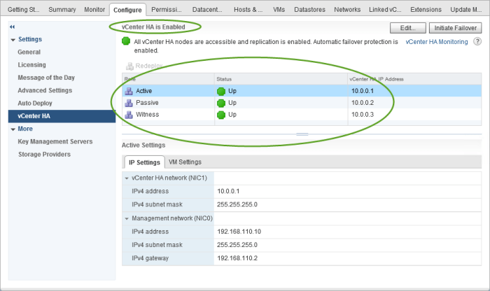
vCenter HA is Enabled
There is one important thing I forgot to point out about the configuration above with the primary vCenter Server in Cluster-A and my Peer and Witness appliances both residing in Cluster-B. Mr. Adam Eckerle (@eck79) quickly made me aware that I did not elaborate more about this configuration posing an issue. The problem is if I were to completely lose all of Cluster-B which contains my Peer and Witness nodes then my active node in Cluster-A will also be down. The thing you want to keep in mind about separating nodes for VCHA is each node should be in its own failure domain.
Always be aware of the risk presented with your vCenter HA configuration; understand where what I like to call the “what if failures” reside. Once you know that then you need to have a plan to mitigate that risk.
So in a perfect scenario what would my vCenter HA environment look like if I had enough resources in my lab environment above for a 3rd cluster? Simple…
- Cluster-A: Active vCenter HA Node
- Cluster-B: Passive vCenter HA Node
- Cluster-C: Witness vCenter HA Node
Three (3) clusters with one (1) VCHA node in each is the ideal model you are looking for.
The vCenter HA Network should span each of those clusters whether I’m using a Standard Switch or Distributed Switch. It won’t matter. Just make sure that network segment stretches all three (3) failure domains.
Remember the following VCHA Best Practices when enabling it. The entire purpose of this feature is to provide high availability in case of a “single” failure. If anything happens to the Active Node you want to make sure everything is in place to ensure vCenter continues to run. Always configure VCHA to avoid single points of failure (SPOF) that would affect these nodes.
- Each VCHA node should be deployed on separate servers to protect against potential HW failures. This includes CPU, memory, motherboard, network, etc.
- Each node should be deployed on separate datastores to limit the impact of a potential disk failure.
- Redundant HW for the entire infrastructure. This includes power & cooling which simply increases overall availability.
- Configure VCHA with one goal in mind…if a failure occurs then that failure should not affect more than ONE (1) node in your VCHA configuration.
Using vCenter HA
There are several key aspects of vCenter HA as far as monitoring and management of the feature goes. First let’s take a look at vCenter HA monitoring. Click the hyperlink for ‘vCenter HA Monitoring’ in the upper right-hand corner for vCenter HA.
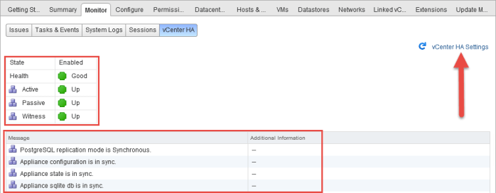
You will be quickly redirected to the Monitor > vCenter HA tab. Here you will see the State of each node as well as any other additional information to ensure the appliances are always ‘in sync’ with each other. If there were any issues you would see that information here. Click the vCenter HA Settings link to go back.
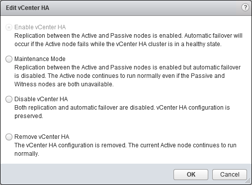
Next click the Edit button in the upper right-hand corner of the page. A new dialog box will appear where you can change the state (or status) of the vCenter HA cluster. By default, as you can see (below) ‘Enable vCenter HA’ is greyed about because it is already enabled. If for whatever reason vCenter HA was disabled you would re-enable it here. There is a ‘Maintenance Mode’ option available in the event the Passive or Witness nodes are unavailable. During this time the ability to failover is disabled but replication between the active and passive nodes remains enabled. You can also completely ‘Disable vCenter HA’. The configuration of the vCenter HA cluster is preserved but everything else becomes disabled. If you wanted to completely remove the vCenter HA cluster you would select the Remove vCenter HA option and click OK. Click cancel for now to return back to the main vCenter HA menu.
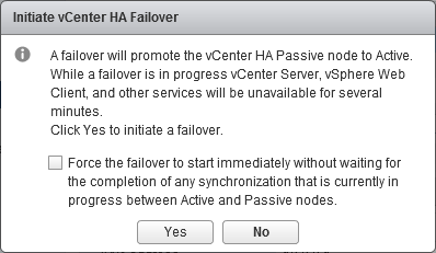
Next click the Initiate Failover button in the upper right-hand corner. The ‘Initiate vCenter HA Failover’ screen will appear. You would use this option if you wanted to perform a ‘planned failover’ of the vCenter Server (Web Client) and other services to the passive node. Yes, during this time vCenter Server services will be unavailable but don’t worry your environment and other VMs will remain intact. Click YES if you want to see what a planned failover looks like.
NOTE: The ‘Force…’ option is available in the event you want to quickly initiate failover without waiting for a final sync to take place between an active and passive node.
I clicked YES to initiate a failover so you can see what takes place during this task. Refresh your browser a few times during the failover process and you will see the vSphere Web Client will become briefly unavailable. Keep refreshing until you see a screen that looks like this.
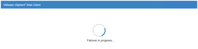
Failover time between appliances will vary based on different environment variables. So what I experience here will be different from what you may experience. I do encourage you to TEST THIS FEATURE after you have enabled it. Don’t just enable it, walk away and then expect it to work the first time you need it. TEST TEST TEST!!! Record your outcomes and make sure everything works. Don’t assume that because something is enabled that it will simply “just work” because you turned it on.
Heck there are times I set my coffee pot to start brewing my coffee for me every morning so its ready for me when I come downstairs. First time I did it I didn’t test it out and when I came downstairs the next morning nothing was there. Things go wrong sometimes, can’t explain it but they do and assuming is what lead to no coffee for me one morning. So always TEST the feature and document your failover process. Never assume something will just work.
After a few short minutes my vSphere Web Client becomes available and I log back into vSphere. Notice the same FQDN and IP Address is being used by your vCenter Server before and after the failover. Look at your web browser URL and double-check from a command prompt by initiating a PING.
Browse back to vCenter HA from the Web Client and notice the order of the three (3) nodes now. Back in Step 16 you saw in order ‘Active, Passive, Witness’ all with a status of UP and their corresponding vCenter HA IP address. Now look at the new order for vCenter HA below. It now states ‘Passive, Active, Witness’. The Passive Node now has the 10.0.0.1 vCenter HA IP address.
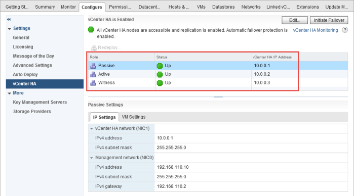
I then initiate another failover to set the ‘Active’ node back to its original status and re-assume the 10.0.0.1 vCenter HA IP Address as part of my ‘failback procedure’ (if I was documenting one for a production environment). Continue to refresh the screen and watch the failover happen again in the reverse direction. I then log back into the Web Client once it becomes ready and verify my vCenter HA status as you see below. The configuration is now back to what it was when I first enabled vCenter HA.

Conclusion
So that is all there is to it when it comes to enabling vCenter HA and spreading the virtual VCSA nodes across multiple vSphere clusters for increased high-availability. As you see in the screenshot in Step 15 the Active node resided in one vSphere cluster while while my witness and passive nodes resided in a separate vSphere cluster. If you have three (3) vSphere clusters could you spread them across all three? Most certainly. It is a very easy process to follow and complete as you just saw above.
What if you are using a single cluster? The best thing to do if you are using a single cluster and enable vCenter HA would be to leverage DRS rules to separate the VMs and keep them on other hosts. Create a single rule, add all three (3) VMs to the rule and choose the ‘Separate virtual machines’ option.
What if you enabled vCenter HA on a single cluster and now have a second (or third) cluster? Very simple. Make sure the vCenter HA Network exists in those other clusters and then simply vMotion the passive and witness appliances to the new cluster(s).
Keep one thing in mind; having a vSphere Distributed Switch will make things easier. If the new hosts in the new cluster use the same vSphere Distributed Switch as your existing cluster then you’re finished at that point. When you add the new hosts to the distributed switch then they should see the same networks as the other cluster assuming your underlying network is configured on those uplinks for your new hosts. Assuming that is all in line then just vMotion the appliances over and the job is done. Bottom line is a Standard Switch would create a little more work for you in the new cluster where as a vDS will make life a heck of a lot easier.
Useful Links
vCenter Server HA Performance and Best Practices – Performance Study Nov-2016 (PDF)
Walkthroughs for vCenter HA (by Adam Eckerle)
I also have a 5-part blog series on Advanced vCenter HA that can be found below:
Part 2 – vCenter HA External PSC Deployment
Part 3 – vCenter HA Load Balancer Configuration
Part 4 – vCenter HA – Deploy vCenter Server
Part 5 – vCenter HA – Enabling vCenter HA
BE SOCIALABLE…SHARE 🙂
