In this blog article I am going to cover how to configure NSX-T routing. In my previous NSX-T blog articles, up to this point, I have covered installing/configuring various components of NSX-T including the NSX-T Manager, host transport nodes, transport zones (Overlay and VLAN), edge nodes and so on. The only difference between those blogs and this one is I will be using NSX-T 2.5 instead of 2.4.
If you are familiar with NSX-v you are going to quickly notice some differences with how components interconnect with one another. The logic is the same but how you accomplish these same tasks in NSX-T is much different. It is very easy to do and understand. In my opinion, it is much easier to do. I will make some references to the NSX-v predecessor to help you bridge that knowledge gap a little between the two. That will most likely help you understand NSX-T if you are still struggling a little.
Before proceeding, the only assumption moving forward is you have a good understanding of NSX-T and the components and are moving towards that next step. If you are still new to NSX-T, I highly recommend reading a few of my previous blog articles before you attempt the routing that I will cover next.
Understanding NSX-T Components
Installing NSX-T 2.4 (Part 1) – NSX Manager
NSX-T Routing Overview
Just a brief overview of routing in NSX-T before we get into the step-by-step configuration. The ‘logical routing’ capabilities in NSX-T has the ability to provide connectivity for both virtual and physical workloads that are in different logical L2 networks. Through the creation of various network components such as segments (aka L2 broadcast domain) and Tier-0/Tier-1 gateways (aka logical routers) in software-defined constructs; they are then embedded at the hypervisor level and ‘abstracted’ from the underlying physical network.
Typical data center traffic is categorized as either North-South (N-S) or East-West (E-W) based on the source and destination of the network flow. Anytime traffic leaves the virtual environment to communicate with devices outside/external, this is referred to as N-S traffic. Network communication between workloads ‘within the data center’ is referred to as E-W traffic.
Single-tier routing is a NSX-T Tier-0 gateway that provides both distributed routing and centralized routing along with other services such as NAT, DHCP, load balancers and so on. The segments (subnets) in a single-tier topology are connected directly to the NSX-T gateway. VMs connected to these segments can communicate E-W as well as N-S to the external data center.
Multi-tiered routing (two-tier routing) also provides distributed and centralized routing with the concept of ‘multi-tenancy’ as part of the routing topology. Here you will find both Tier-0 and Tier-1 gateways; this design allows provider admins (Tier-0 and tenant admins (Tier-1) total control over their respective services as well as policies.
I’m going to show you both starting with single-tier routing first in this blog article. Multi-tier routing will be in a future blog article.
Single-Tier Routing
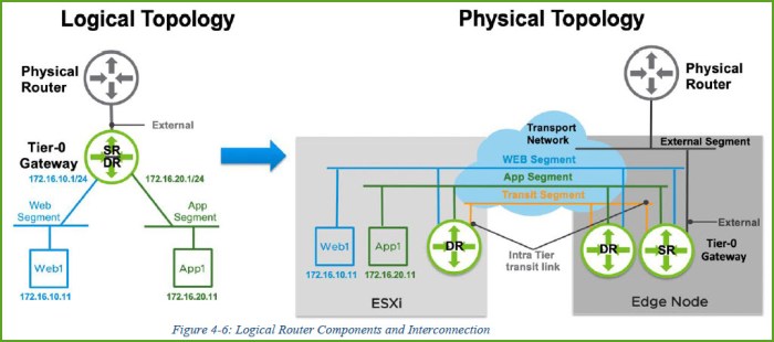
In this exercise I’m going to configure a Tier-0 logical router (LR) with two connected L2 segments. One segment for APP and another for WEB. The logical topology that I will deploy is found in Figure 4-6 on Page 49 of the NSX-T Reference Design Guide 2.0. The same graphic on that page is below. The external network segment for my environment is the 192.168.110.x /24 network.

Let’s get started. Log into the NSX-T manager UI and we will go from there.
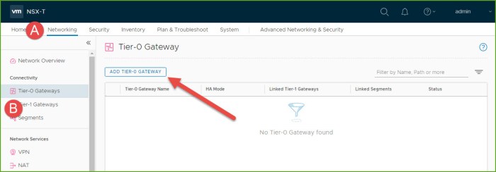
- Select the Networking menu and then select ‘Tier-0 Gateways’ beneath the Connectivity section. Click on the ‘Add Tier-0 Gateway’ button.
- Enter a name for the gateway and select the Edge Cluster from your environment. Click Save.
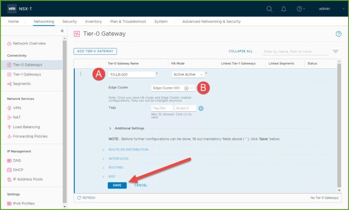
- Select NO when prompted to continue configuring the Tier-0 Gateway.

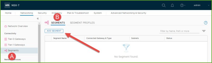
- Select Segments and then click on Add Segment.
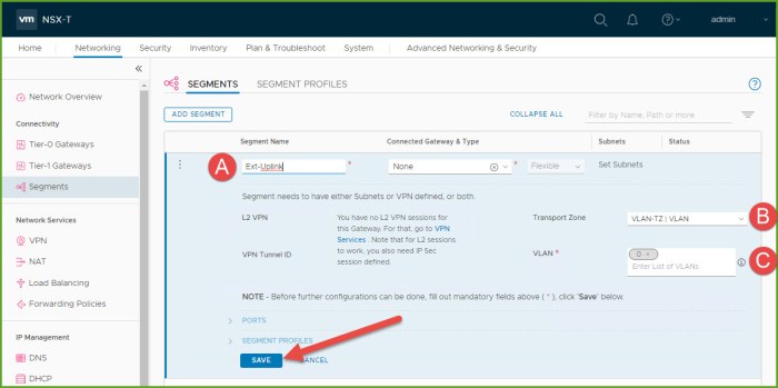
- Provide a name for the uplink segment, select the VLAN backed Transport Zone (TZ) for your environment and then enter VLAN 0. Click Save. Next you will be prompted to continue configuring the new segment, click NO.
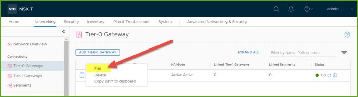
- Return to the Tier-0 gateway that we created previously and select Edit from the options menu.
- Expand Route Re-distribution and select Set.

- Select the following options for the Tier-0 Subnets and Advertised Tier-1 Subnets. Click Apply.
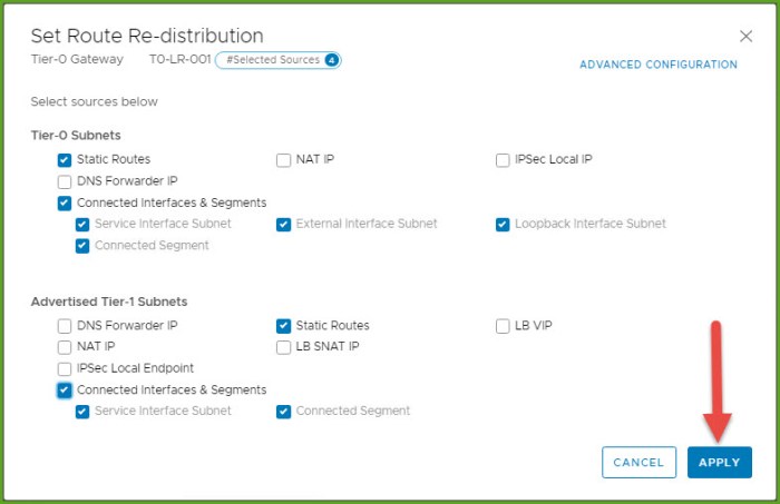
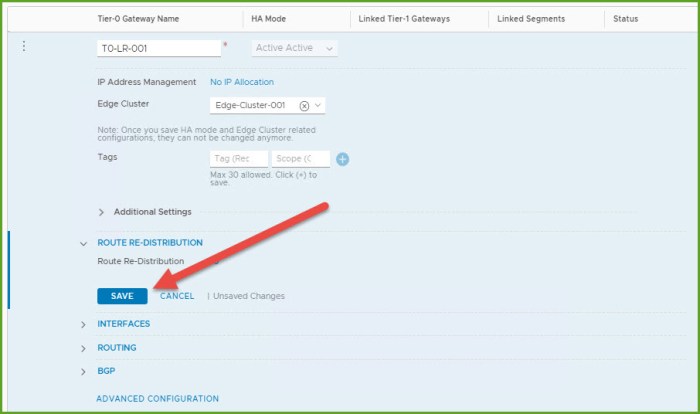
- Click Save under Route Re-Distribution.
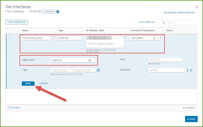
- Expand Interfaces and select Set.

- The Set Interfaces dialog box will appear, select the Add Interface button. Here we are going to connect the new T0 router to the external segment we just created. Provide a name for the internal, select External for type, provide IP address for interface, select the external segment, select an Edge node and click Save and then Close.
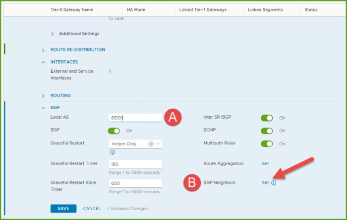
- The next step requires you to know a little bit about BGP. I’m going to configure eBGP which means the local AS will differ from the BGP neighbor remote AS. Here I enter the Local AS 65101 for my T0 router and then click Set next to BGP Neighbors.
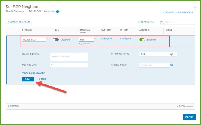
- The Set BGP Neighbors dialog box will appear, select the Add BGP Neighbor button. Provide the remote IP address for the remote physical router, remote AS and click Save and Close.
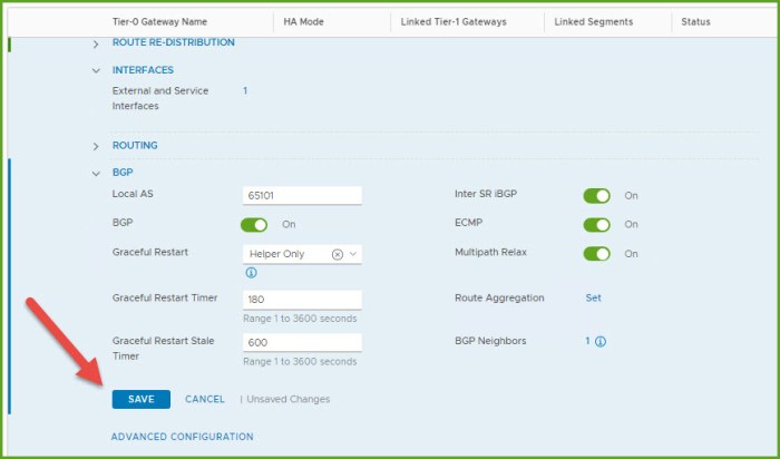
- Select Save and then Close Editing once the changes are finished being saved.
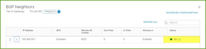
- Go back into your configuration, select the ‘1’ next to BGP neighbors to get a status of the BGP peering. Refresh a few times until you see the status change to UP. If it does not say UP you should start investigating the parameters needed to establish the adjacency. Status for the new Tier-0 gateway should be UP as well.
- Now we are going to create the WEB (172.16.10.x /24) and APP (172.16.20.x /24) segments based off of the logical diagram I am working with from design guide. Select Segments and then Add Segment button. Provide a name for the segment, select the T0 gateway, ensure the Overlay TZ is selected and select Set Subnets.

- The Set Subnets dialog box will appear. Click on Add Subnet. Enter the IP address for the segment default gateway that will be used by the workloads. Click Add and then Apply.

- Review the segment settings and select Save. When prompted to continue configuring the segment select No. Test your connectivity. Open a command-line and ping the new gateway IP address for the segment, you should get a response.

- I then repeat steps 16-18 to create the APP segment with a gateway IP address of 172.16.20.1 /24. Very the status of the two new segments, both should be UP and you should be able to ping the two new gateway IPs.

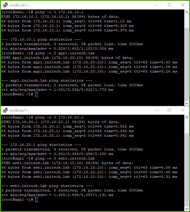
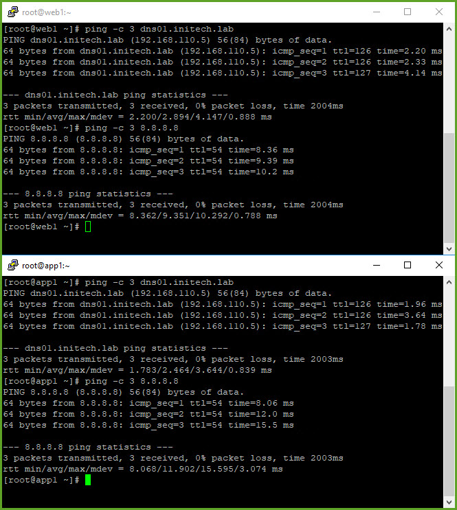
- My WEB and APP virtual machines are already deployed. From vSphere I configured my VMs to use their respective network segments; both are configured with static IPs. I begin to test connectivity between the VMs as well as any resources on networks external to my NSX-T environment. As you can see my VMs can communicate East-West (between L2 segments) and North-South (my DNS server on my underlay and public Internet).
That wraps up single-tier routing in NSX-T. Very simple and straightforward. You can read more about it starting on Page 44 of the NSX-T Reference Design Guide.
Routing Concepts Review
Just a quick review of some of the routing concepts with NSX-T and specifically single-tier routing. The single-tier topology is one that implies that the T0 gateway being deployed will provide both N-S and E-W network connectivity. VMs connected to L2 segments are then attached to the T0 gateway can communicate with one another E-W and other resources N-S just as we witnessed above with the Web and App VMs.
There is a distributed routing (DR) component for this T0 gateway; this instance is created as a kernel module and will function as a ‘local gateway’ for the workloads connected to these segments. There is a logical interface (LIF) on the gateway that is used as the default gateway. Apply the gateway for the L2 segment, configure your VMs properly and traffic will begin to flow as expected.
Segments in NSX-T are known as Logical Switches in NSX-V. They were then connected to a LIF on a logical router (DLR or ESG) which also had a static IP associated with the LIF and functioned as the default gateway for the logical switch segment. The DLRs and ESGs in NSX-V were actual VMs deployed in a dedicated vSphere cluster depending upon the design of that intended environment; with NSX-T this is no longer the case.
There are two distinct NSX-T components…the DR (distributed router) and SR (services router). In vSphere, the ESXi host(s) have the DR component only whereas the Edge Node(s) have a merged DR/SR component. Figure 4-6 on page 48 of the NSX-T Reference Design Guide provides the logical and physical topology of how this all ties together. This same image is below.
East-West routing is distributed by the hypervisor (aka host transport node); each hypervisor in the TZ is running a DR at the kernel level. When they are created they exist on the edge node as an SR and not distributed as a DR. Below is a list of some of the SR services that can be enabled in NSX-T:
- Gateway Firewall
- DHCP
- VPN
- NAT
- Bridging
- Service Interface
- Physical network connectivity
- Metadata Proxy
Want to learn about Two-Tier Routing? Check out my other blog article!
Useful Links
NSX-T Reference Design Guide 2.0 (PDF) – for versions 2.0 – 2.5
VMware NSX-T Data Center Documentation
VMware NSX Training and Demos (YouTube Channel)
VMware NSX-T 2.5 Release Notes

2 thoughts on “NSX-T Single-Tier Routing”