In Part 1 of my NSX-T 2.4 installation series, we covered the basis of the deployment for the NSX-T data center for vSphere. This included deploying the NSX Manager virtual appliance, deployed/configured the cluster nodes and lastly added a Compute Manager (vCenter Server).
You might be asking, why not just deploy NSX-T 2.5 right? I have two valid justifications for this. First being the fact I would like to continue where I left off with Part 1 of my mini-blog series which started before NSX-T 2.5 was released. Second, I want to complete the 2.4 installation so I can then segue that into a future blog where I will upgrading to NSX-T 2.5. Always a method to my madness! I will reference the installation guide quite a bit as I move along here to make it easier for you to quickly find the information you need.
Before I start with Part 2 and deploy anything, let’s review the topology that I’m using in my lab as well as some requirements which I will summarize from the documentation. All very important tasks that you should also follow to ensuring NSX-T is deployed correctly. Read the manuals multiple times and create a worksheet (checklist) to stay organized. The workflow that I am going to cover for vSphere will cover the following:
- NSX-T Transport Zones (Overlay & VLAN)
- IP Pools
- NSX Profiles
- Host Transport Nodes
- NSX Edge Transport Nodes (Edge VM)
- NSX Edge Clusters
My main goal here is to provide some insight as to what the installation and configuration process may look like for you. My lab design is most likely nothing close to what you are planning to do in your environment so proceed with caution. My recommendation would be for you to review all of the NSX-T documentation and then engage with professional services that will help you plan and design your environment to fit your needs. My article will help familiarize you with the concept and logic behind the installation (including screenshots) so you know what to expect.
Lab Environment Review
Just a quick review of what I am working with in my lab environment. This is a nested environment that I am running on my kicka$$ lab server. My management components are VMs deployed on my standalone ESXi host including my vCenter Server (VCSA), the NSX Manager and a couple Windows 2016 Servers running services such as DNS, DHCP and Active Directory.
As for the vSphere management components and nested ESXi hosts, here is what I am working with.
- vCenter Server (VCSA) 6.7 U2a (6.7.0.31000) – Build 13639324 (Release Notes)
- ESXi 6.7.0 (EP10) – Build 13981272 (Release Notes)
- Each nested host is configured with:
- Four (4) vCPU
- 12 GB (12,288 MB) of memory (reserved)
- Four (4) 10GbE (vmxnet3) network adapters
- One four (4) node vSAN cluster for compute.
- One two (2) node Edge cluster for my NSX Edge VMs.
- Each nested host is configured with:

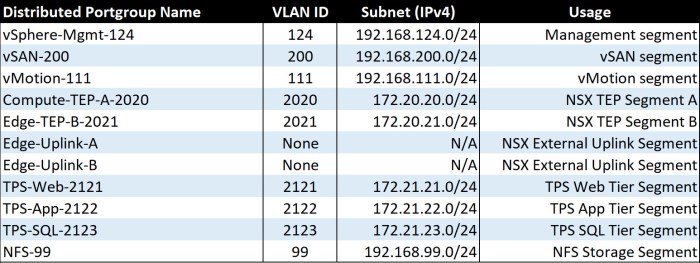
The table below is a summary of the network segments in my nested lab. Two (2) of the four (4) network adapters on my nested ESXi hosts (6) are connected to my vSphere Distributed Switch (vDS); two (2) are unused (unassigned) which I will eventually configure for use on my N-VDS.
- Management Segment: vCenter Server, NSX Manager, DNS/DHCP/AD Windows Servers, ESXi host management vmkernel adapters.
- vSAN Segment: vSAN vmkernel adapters; found only on my four (4) compute hosts.
- vMotion Segment: vMotion vmkernel adapters for all ESXi hosts.
- I have a 3-tier application called TPS where I have VMs connected an online.
- NFS storage segment: Two (2) node edge cluster storage.
- Three (3) NSX related segment which we will dive into a little later but I have two (2) TEP Segments and a single (1) External Uplink segment.
- Each of the ‘Edge-Uplink’ port groups below have a single active pNIC (vmnic) defined in the teaming and failover policy.
- Edge-Uplink-A -> Uplink-1 (vmnic0)
- Edge-Uplink-B -> Uplink-2 (vmnic1)
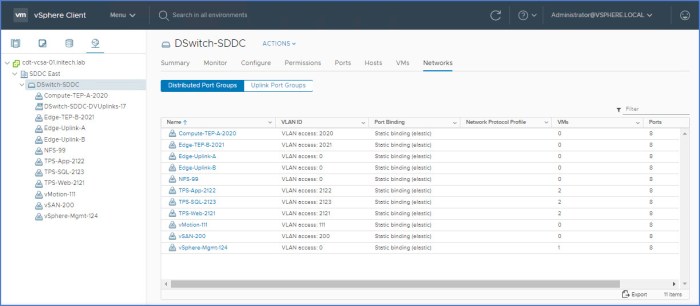
Below is a screenshot of the vSphere Distributed Switch (vDS) in my nested lab. This vDS is configured to use two (2) physical uplinks per ESXi host and spans both clusters.
- Uplink 1 – vmnic0
- Uplink 2 – vmnic1
There are two (2) unused physical uplinks on each ESXi host which I will use during the deployment/configuration of the N-VDS which we will deploy here shortly; will use vminc2 and vmnic3 in that procedure.
Prep for Installation – Requirements
Before installing anything it is always good to get in the habit of knowing and fully understanding the requirements for deployment. The NSX-T installation guides have you covered and outline all of the requirements for deployment.
NOTE: NSX Manager is already deployed in my environment which I covered during Part 1 of this blog series which you can find here. You should also review the ‘Deployment, Platform and Installation Requirements’ section on pages 25-26 of the NSX-T 2.4 Installation Guide (PDF).
NSX Edge (VM) Installation Requirements
The installation requirements for the NSX Edge (VM) deployment are outlined on pages 28-29 of the NSX-T 2.4 Installation Guide (PDF). To quickly summarize:
- We are going to be working with a virtual appliance (OVA/OVF format). Remember this type of edge deployment is only supported on ESXi (not KVM). ISO deployments are also supported but we will not be doing that here.
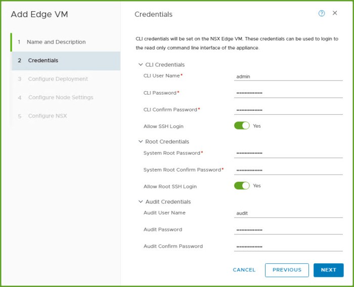
- Appliance passwords must be complex:
- Minimum of 12 characters.
- Upper and lower-case letters.
- At least one (1) digit and one (1) special character.
- Must contain at least five (5) different characters.
- No dictionary words, no palindromes and more than four (4) characters sequence is prohibited.
- Come up with a DNS hostname (FQDN) for the each edge appliance. I’ll only be deploying two (2) Edge VMs in my lab. Do not use any invalid characters in your hostname and if you do by accident, the edge VM will boot an assume the hostname ‘localhost’. If this happens to you then this is an indicator that you may have used an invalid hostname character.
- The NSX Edge VM will have the VMTools installed. Do not uninstall or upgrade the tools at any time. Leave them be.
- Edge VM Resource (System) requirements are determined by appliance size.
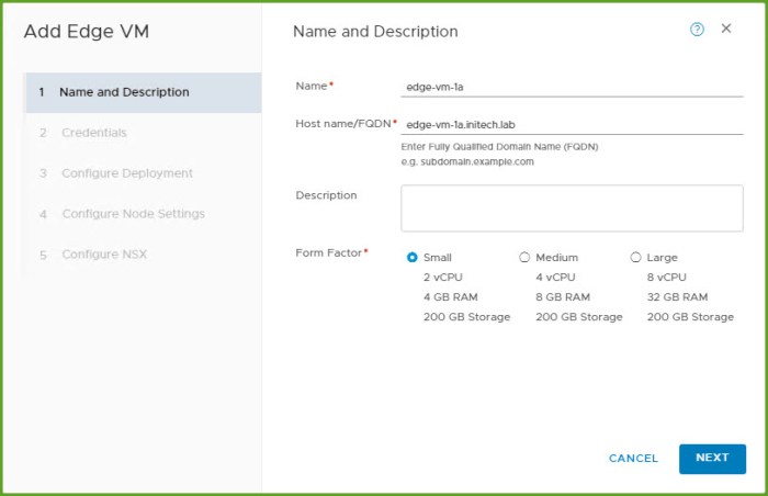
- Edge Small – 2 vCPU, 4 GB memory (ideal for lab and POC environments).
- Edge Medium – 4 vCPU, 8 GB memory (suitable for most production environments).
- Edge Large – 8 vCPU, 32 GB memory (ideal for large environments that utilize load balancing)
- All three (3) edge instance types above require 200 GB of disk space and are deployed with VM hardware version 11 or later (vSphere 6.0 or later).
- NSX Edge VM CPU Requirements require the underlying platform to have the following:
- CPU must support AESNI (AES New Instructions).
- CPU must have 1 GB of Huge Page support.
- CPU hardware types are summarized in a table on the bottom of Page 17 of the NSX-T 2.4 Installation Guide.
- NSX Bare Metal CPU requirements (even though I will not be deploying bare metal in this lab). Here they are in case you are planning for a bare metal deployment.
- Eight (8) core CPU w/ 32 GB memory and 200 GB disk space.
- CPU must have AESNI capabilities and 1 GB Huge Page support.
- The same CPU hardware types outlined for the Edge VM are also listed for the bare metal Edge. Additional hardware and server requirements are outlined on pages 18-20 of the NSX-T 2.4 Installation Guide.
Ports & Protocols
All of the ports and protocols required for the communication paths are summarized in several tables in the NSX-T 2.4 Installation Guide from pages 20-25. This includes ports and protocols required for NSX Manager as well as NSX Edge communications. When you review these tables in the documentation be very aware of the ‘Source’ and ‘Target’ columns as they pertain to the specific Port ID and Protocol (TCP or UDP) being used.
Design Considerations
Here is a summary of some common deployment scenarios/considerations that should be reviewed thoroughly prior to installation.
- Management
- NSX-T components require IP connectivity and VLANs; place on new subnet (VLAN) or on existing management segment.
- Controller operations are completely independent of vSphere (ESXi); ensure the controllers have reliable connectivity and low latency w/ the NSX- T domain.
- Reserve the resources (CPU, memory, thick provisioned disk, etc.) for the management VMs to ensure predictable operational consistency. Plan ahead so make sure the ESXi hosts that will support these virtual appliances have ample resources.
- vCenter Server Appliance(s)
- NSX-T Managers and Controllers
- Edge Node VMs
- High Availability – avoid single-point-of-failure (SPOF).
- Controllers – make sure the controllers (3) are running on different hypervisor hosts and not the same host simultaneously; utilize DRS anti-affinity rules.
- Edge Node VMs – run these VMs on separate hosts; utilize DRS anti-affinity rules.
- Review the Edge design guidance for connectivity and availability recommendations including services such as ECMP and/or any stateful dependencies related to the clustering of the Edge.
- N-VDS
- Remember the N-VDS can co-exist with another N-VDS or a traditional vSphere Distributed Switch (vDS) but each requires their own subset of pNICs (physical uplinks) and cannot be shared.
- The N-VDS can only have one (1) team policy so plan how this configuration aligns with your requirements before implementing.
- Deployment Model Options
- Collapsed Management and Edge Resources Design – this means your design will include a single cluster for all management and edge resources (VMs) with the compute clusters (domains) being completely separated. Reference this design starting on page 179 of the NSX-T Reference Design Guide 2.0.
- Collapsed Compute and Edge Resources Design – same concept as the previous model but in this situation the Edge VMs and the Compute (workloads) are running on the same cluster(s). The Edge VMs are closer to the application in this situation. Reference this particular design starting on page 186 of the NSX-T Reference Design Guide 2.0.
- Dedicated Management and Edge Resources Design – commonly referred to as the ‘Enterprise Design’ for this particular model. Herel each workload type for management, edge and compute run in separate/dedicated hypervisor clusters.
NSX-T 2.4 Deployment & Configuration
Now that we covered some very important design and deployment topics we can now continue with the NSX-T 2.4 installation and configuration.
Transport Zones – Overlay & VLAN
I am going to create two (2) transport zones (TZ) so you can see the process for creating both; one (1) Overlay transport zone and one (1) VLAN backed transport zone. Remember a TZ dictates which hosts and VMs can use particular networks. These TZs can span one or more host clusters. In this case we are working with ESXi host clusters but KVM hosts can also be used. A couple key things to remember here before we begin.
- The Overlay TZ is one that can be consumed by the NSX Edges and the host transport nodes. The N-NVDS will be installed on the host(s) anytime a new host or NSX Edge transport node is added to this Overlay TZ.
- The VLAN transport zone is also used by the NSX Edges and the host transport nodes and more specifically their VLAN backed uplinks. Anytime an NSX Edge is deployed to this VLAN TZ a ‘VLAN N-VDS’ will be installed on the host or NSX Edge.
- When either TZ type is created, an admin must provide a name for the N-VDS that will be initiated on the transport nodes (name it anything you want it to be but I recommend giving it a name that will help describe its function or what type of workloads it may be supporting in your environment).
- Enhanced Data Path is a ‘network stack mode’ for ESXi 6.7 hosts or higher; used for enhanced performance benefits. This mode can be used for both Overlay and VLAN backed TZs.
- Requires supported NIC cards and drivers.
- Reference the VMware Compatibility Guide to validate support for your system configuration:
- ‘What are you looking for’ drop-down menu: IO Devices
- Release Version: vSphere 6.7 or later
- I/O Device Type: Network
- Features: N-VDS Enhanced Data Path
- Brand: If you know which brand you intend on using.
Now let’s move onto creating the Transport Zones (TZ) for my NSX-T environment.
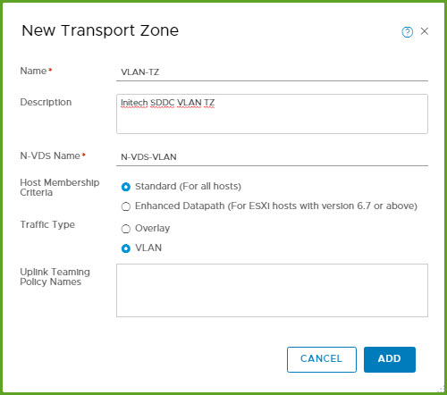
- Log into the NSX Manager UI (URL) and then select ‘System > Fabric > Transport Zones > Add’

- Next I’m going to create the ‘Overlay-TZ’ and use ‘Standard’ for Membership Criteria. Despite the fact my hosts are running version 6.7, this is a nested environment and I do not have supported NICs or drivers for Enhanced Datapath. The N-VDS Name will be named ‘N-VDS-Overlay’. Click Add.

- Next create the ‘Overlay-VLAN’ TZ and use the ‘Standard’ host membership option here as well. The N-VDS Name will be named ‘N-VDS-VLAN’. Click Add.
IP Pool for TEPs
Next we need to create an IP Pool for the NSX TEPs (Tunnel Endpoints) which will be configured on the ESXi hosts when we prepare the cluster(s). If you performed an NSX-V installation at some point you likely did the same thing. You could also use DHCP if you have a separate VLAN and TCP/IP segment pre-configured and ready to go ahead of this (don’t forget DHCP Relay Agent configuration on your physical network).
Here are the steps to create a TCP/IP pool for the NSX TEPs. You can configure a specific IP Range or IP Block. I will configure these IP Pools as ranges. Regardless of which option you plan to use, reference your planning documentation where you should have the TCP/IP range (subnet), it’s CIDR annotation and gateway IP for your TEP segment(s). The VLANs should be configured on the physical network and be configured on the appropriate uplinks on the ESXi hosts.
I have two (2) TEP segments pre-configured in my lab environment. My plan is to map my ‘Compute TEP A’ network segment to ‘TEP-A Pool’ and my ‘Edge TEP-B’ networking segment to ‘TEP-B Pool’ respectively.
- TEP-A Segment: VLAN 2020 / 172.20.20.0 /24, Default Gateway 172.20.20.1
- TEP-B Segment: VLAN 2021 / 172.20.21.0 /24, Default Gateway 172.20.21.1
Prior to starting this I validate network connectivity with these VLANs by pinging the DGs on each segment from my ESXi hosts. Everything checked out and I’m ready to go!
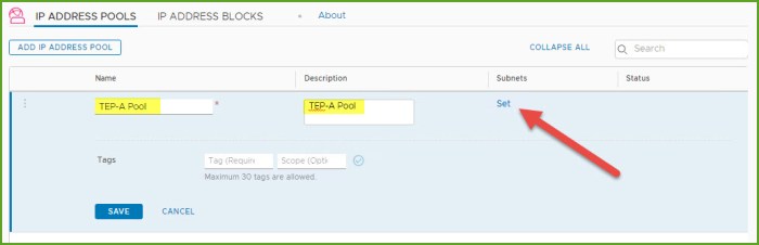
- From the NSX Manager UI (URL) select ‘Networking > IP Address Management > IP Address Pools’ and select ‘Add IP Address Pool’.

- I provide a ‘Name’ and ‘Description’ in the necessary fields and then click ‘Set’ in the Subnets column.
- Select the ‘Add Subnet’ drop down menu and select the ‘IP Ranges’ option.

- The window will quickly refresh and then you must enter the IP Ranges, CIDR annotation and Gateway IP for the intended range. Let’s just say I need to create a block of 64 addresses in this example. I enter all the information and click Add.

- Review the information once more and then click Apply.

- Lastly click SAVE.
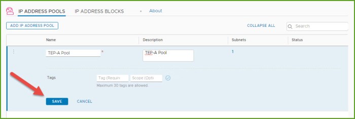
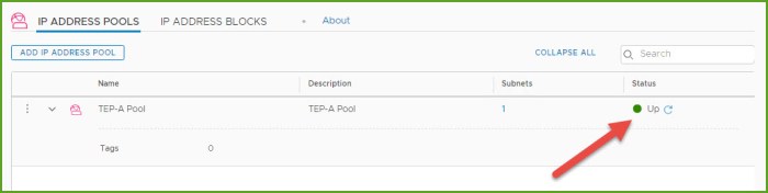
- Confirm the IP Pool has been created and verify the Status column states Up.
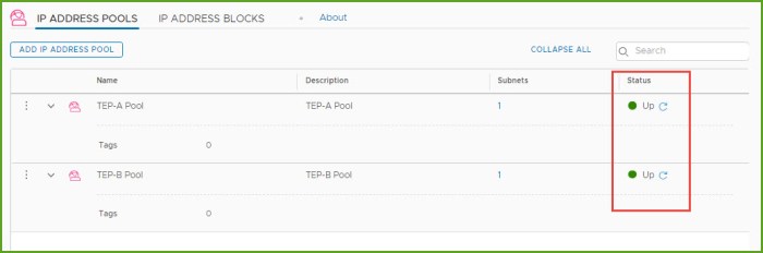
- Repeat steps 1-7 to create any additional IP Pools. I’m going to create a second IP Pool called ‘TEP-B Pool’ which is VLAN 2021, CIDR 172.20.21.0 /24 network. When I’m finished my two pools appear in my inventory as seen below.
NSX-T Profiles
Next thing I want to review and/or configure are the profiles. There are five (5) profile types that you will find in the NSX-T Manager UI. We are going to start with two (2):
- Uplink Profiles
- Transport Node Profiles
Remember you should have a plan in place for how the transport nodes (hypervisor hosts) to connect to the physical environment. Uplink Profiles logically (software-defined) describe how the underlying physical uplinks should be utilized or configured. Profiles maintain consistency for the deployment. There are four (4) pre-defined, out-of-the-box Uplink Profiles; you can use one these default profiles or define one of your own. I’m going to create two (2) here so I can demonstrate some of the different settings that you can use.
Transport Node Profiles define how the node will map to a specific ‘Transport Zone’ and which N-VDS it should associate with. You won’t find any default profiles here.
Uplink Profile
- From the NSX Manager UI, select ‘System > Fabric > Profiles > Uplink Profiles’ and then click Add.

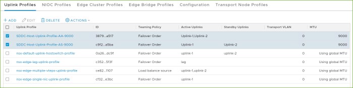
- In the ‘New Uplink Profile‘ dialog box, I enter the information I want to use for my network teaming along with a specific MTU size that I am using (9000). I provided a unique name and a brief description. The ‘AS’ in the name stands for ‘Active/Standby’ so I can quickly identify how this profile is configured. Click Add.

- I’m going to create a second uplink profile for an ‘active-active’ uplink config and click Add when I’m finished.

- I now have two (2) uplink profiles as you can see below. One profile for Active/Standby and one for Active/Active.
Transport Node Profile
Earlier I created two NSX-T Transport Zones. One for an Overlay and one for VLAN. In this segment I’m going to create a Transport Node profile for each.
- From the NSX Manager UI, navigate to ‘System > Fabric > Profiles > Transport Node Profiles’ and click Add.

- In the ‘Add Transport Node Profile’ dialog box, enter a name for profile (description optional) and select an available transport node and move it from left-to-right. This first profile is for the nodes that will participate in the Overlay TZ. Review the entries and then click on ‘N-VDS’ at the top.

- Next I will apply the settings for the N-VDS that will be deployed for the Overlay TZ. The names for the N-VDS come from when the TZ’s were created earlier. Same with the IP Pool names and so on. I provided the names of the physical uplinks that I want to be used and when finished click Add.

- I repeat the steps now to create my 2nd Transport Node Profile for the profile to be used for the VLAN transport zone. Click ‘N-VDS’ at the top.

- I apply the settings for the N-VDS that will be deployed with the VLAN based TZ. Notice the ‘IP Assignment’ is greyed out because a TEP is not necessary for this transport zone type. TEPs are used for Overlays. I enter the necessary uplink names for the devices and click Add.

Host Transport Nodes
Next I am going to configure my two clusters for NSX. Very quick and easy now that we have our Host Transport Node profiles.
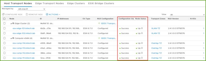
- Navigate to ‘System > Fabric > Nodes > Host Transport Nodes’ and select the drop down menu and choose my vCenter Server. Expand the clusters to view the ESXi hosts.
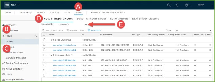
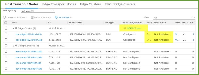
- I first select my Edge Cluster and then select ‘Configure NSX’. In the ‘Configure NSX’ dialog box I select the Deployment Profile from the drop down menu and click Save.

- The configuration in NSX will begin on the cluster. Node status will eventually change from ‘Not Available’ to ‘NSX Installation In Progress’ and finally SUCCESS.
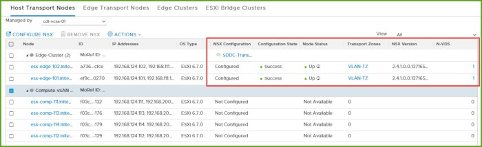
- When the process completes the Configuration State will state ‘Success’ and the Node Status will state ‘Up’ along with the NSX Version that is deployed.
- I then repeat this procedure for my other cluster which happens to be my Compute cluster where my workloads are running and where I intend to deploy my Overlay. I choose the ‘SDDC-Transport-Overlay’ profile for the cluster and wait again just I did above.
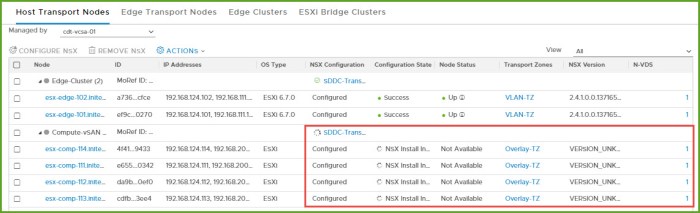
- The installation completes and my Host Transport Nodes are now prepared.
Edge Transport Node Deployment (Edge VM)
Next I am going to deploy two (2) Edge Transport Nodes (Edge VMs) and then configure an Edge Cluster.
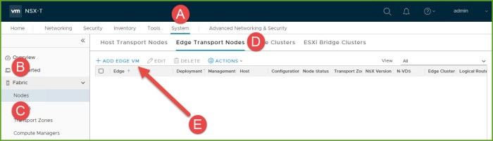
- From the NSX Manager UI navigate to ‘System > Fabric > Nodes > Edge Transport Nodes’ and select Add Edge VM.
- In the ‘Add Edge VM’ dialog box, enter the Name, Host name (FQDN) and form factor size (description optional). Click Next.
- Next I configure the credentials for my CLI user, root account password and an audit username and password. I also chose to allow SSH. Click Next.
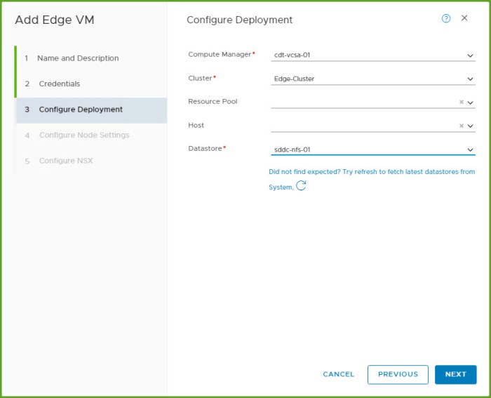
- On the Configure Deployment section I select the Compute Manager (my vCenter Server), my target cluster and datastore. The host resource pool and specific host is optional. If the target cluster is not running vSphere DRS an admin should select a specific host for deployment. Click Next.
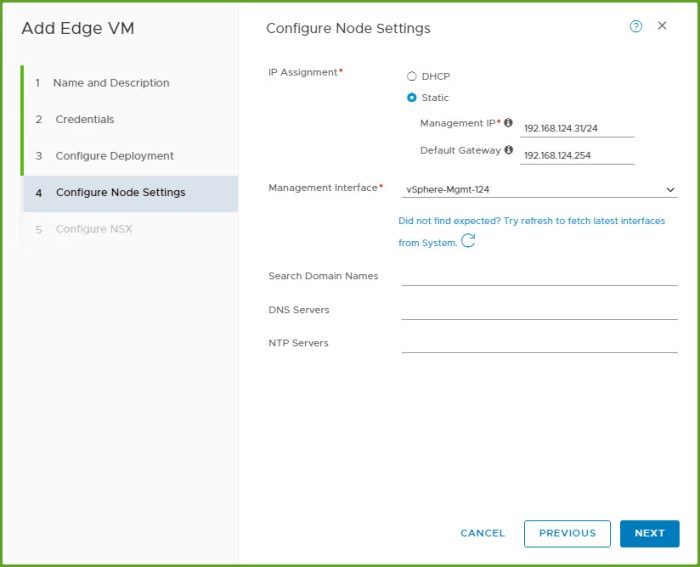
- On the Configure Node Settings I select my IP Assignment (static address and validated DNS name resolution) and enter the Management IP information for my Edge VM. Then select the management interface port group, in this case my existing Management VLAN (subnet). The remaining information is optional. Click Next.
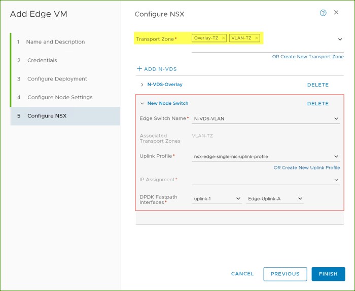
- On the Configure NSX (final page) I select my Transport Zones along with my N-VDS information for each corresponding TZ. Here I configure the ‘N-VDS-Overlay’ first, click ‘+ADD N-VDS’ and then complete the information for my ‘N-VDS-VLAN’ next. Review the information and click FINISH.

NSX Edge Cluster
Now that I have two (2) Edge VMs deployed for my environment I can now group them logically by creating an NSX Edge Cluster. Having a multi-node Edge Cluster in your environment ensures at least one (1) NSX Edge is available (accessible).
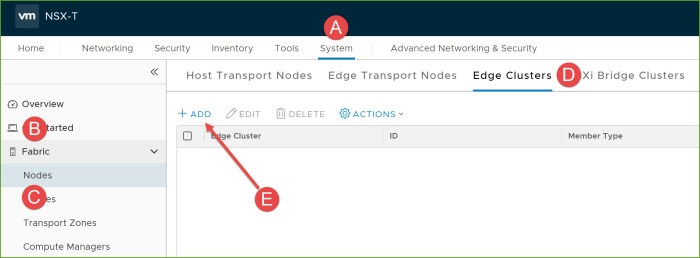
- From the NSX Manager UI navigate to ‘System > Fabric > Nodes > Edge Clusters’ and then click +Add.
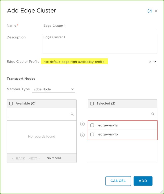
- In the ‘Add Edge Cluster’ dialog box, enter the name of the Edge Cluster, select an Edge Cluster Profile and then move the Edge Transport nodes from ‘Available’ to ‘Selected’ and click Add.
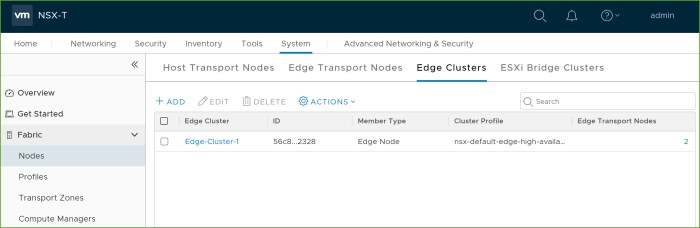
- Review the Edge Cluster that you just created in the inventory.
Conclusion
So there you have it, a quick overview of installing various NSX-T components in a lab environment. I hope it helped familiarize you with the process and give you a little preview as to what you might expect on your NSX-T journey whether you are preparing for an exam or planning on deploying it for future production use.
In my opinion, being successful really starts with how you prepare. Preparation goes a long way and the amount of time you allow yourself to do this will put you on a path where you will have positive results. So be proactive, not just with something like NSX but with anything you might be doing.
I’m a big sports fan and this time of year NFL football and hockey are my two favorites to watch. You see it every year, teams that are loaded with talent but for some reason cannot put things together. My guess is they assumed all the talent would carry them onto to success and did not have to prepare much. Then they see a team viewed as a “lesser opponent” achieve greater success. Some chalk that up to “luck” but I’d put my money on the fact is they put the extra work in to prepare.
If you are preparing to go down the road of true software-defined networking and use VMware NSX, get ahead of it. Download the necessary documentation, talk to various resources available online and in your local pod of technical resources which will ultimately set you and your team up for success!
Important Links & Downloads
VMware NSX-T Data Center Documentation (VMware Docs) – central resource for all things NSX-T related.
VMware NSX-T Reference Design 2.0 (PDF Guide) – in my opinion the holy grail of design guides.
VMware NSX / Network Virtualization Blog Site – awesome blog site for what’s new around NSX features, capabilities, security, design & deployment operations, events possibly in your area and much more.
VMware NSX Training and Demo (YouTube Homepage) – many great videos and clips on here that will help you get a better understanding of NSX-T.

Hi – Awesome post again. Very helpful. Just wonder about your nested setup, is your vCenter (and vSAN) installed on nested host(s) in this case? I could not find your DC in your vSphere Lab Environment picture.
LikeLike
Yes I have a single, physical lab host where I run everything nested. My VCSA, ESXi hosts and Windows Servers, including DC, is all running directly on my standalone ESXi lab host. I also use a virtual router appliance called pfSense to create/manage my VLANs (subnets) for other various networks that I need such as vMotion, vSAN, TEPs for NSX and so on. Very easy to use and deploy.
LikeLiked by 1 person