Before I get into Part 2 of my Installing NSX-T mini blog series, let’s review some NSX-T components. There are some differences between NSX-T and NSX-V that everyone should be aware of. This blog article is not intended to do a full side-by-side comparison between the two but I will point out some differences or similarities along the way. My main goal here is to increase your understanding of NSX-T and hopefully help you become more successful whether you’re preparing for a production deployment, have an upcoming POC where you need to be successful or simply looking to increase your knowledge of VMware NSX.
NSX-T is designed with a lot of flexibility which enables it to meet the needs of various app frameworks, architectures, multiple endpoints and technology stacks. Aside from meeting the demands in a vSphere environment it also addresses the needs for containers, bare metal deployments, 3rd party hypervisors and public clouds. Leveling the playing field from a network perspective, IT teams and development teams can now align the network with what suits their applications the best. So when you think of NSX-T think “any endpoint, any site, any cloud.”
The application is the focal point when it comes to NSX-T and it’s architecture. Networking and security remains consistent regardless of how the app was built; whether it be a microservice based app framework or a traditional waterfall model. It does not matter. It is 100% app-focused, app-centric.
Highlighting the design is the uniform approach to consistency that encompasses everything from multi-hypervisors to containers to hybrid-cloud. IT admins and developers are now in a unique position and can place the application wherever it makes the most sense; the operational networking and security will follow. Think of it as the “NSX Anywhere” architecture whereby the network is completely decoupled from the underlying infrastructure, meaning that is has been designed not to require anything in particular aside from IP-to-IP connectivity.
NSX-T Architecture Components
Has anyone ever asked you what is VMware NSX-T or how it is composed? The answer is…NSX-T is a comprehensive set of networking services (routing, switching, load balancing, firewalling, etc.) which can assembled programmatically and subjectively.
There are three (3) planes that make up NSX-T: management, control and data. Each plane is composed by a node.
- Management Plane contains Management Nodes.
- Control Plane contains CCP (Central Control Plane) Nodes (aka controllers).
- Data Plane contains Transport Nodes.
The physical infrastructure that is in your data center now is going to remain in place. There are a few requirements and recommendations but by no means is it a rip-n-replace effort. In fact, it’ll enhance networking in such as way that you can consume it on-premise very much the same way it is consumed in the public cloud.
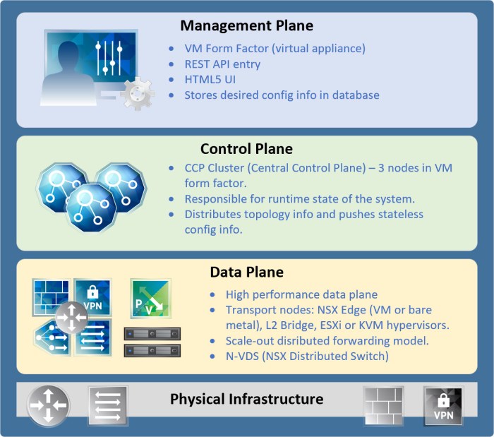
Management Plane
NSX-T Manager is at the core of the management plane and provides a wide system view of everything involved. It is a single API entry point responsible for maintaining things such as user config, user queries as well as operational responsibilities for the three planes (management, control and data). Brief outline of responsibilities for the Management Plane:
- Entry point for user config via the NSX-T User UI or using RESTful API.
- Saves the desired configuration as well as statistical information.
- Stores the desired configuration in its local database. This config is then pushed by NSX-T Manager to the control plane which then converts to an active config at the data plane level.
- All NSX-T components have something called a MPA (Management Plane Agent) which connects that components back to the NSX-T Manager.
Control Plane
Control Plane can be easily remembered by referring to the NSX-T Controller(s). This plane is responsible for calculating the “run-time state” of the system based on the config that was provided by NSX-T Manager (management plane). It also communicates with the data plane and is therefore responsible for distributing topology info and pushing stateless config information to the forwarding engines. The control plane is composed of two (2) parts:
- CCP (Central Control Plane) employs a cluster of VMs called CCP nodes. The purpose of the cluster is to provide redundancy and scalability of resources.
- Any failure here at the CCP level will not affect data plane processes.
- User traffic does not traverse the CCP cluster.
- LCP (Local Control Plane) is found on the transport nodes which use the LCP to connect and communicate with the CCP. The programming for the forwarding entries occurs here.
Data Plane
The data plane is where all stateless forwarding (packet alteration) takes place based on tables created by the control plane. Packet level stats are found here as well as topology info which is then reported from the data plane up to the control plane.
Here you will find NSX-T transport nodes which are hosts running the LCP daemons and forwarding engines. This is also where you will find the new N-VDS (NSX Virtual Distributed Switch) which is unique to NSX-T (more on this later).
Here is a brief rundown of the transport node types and other components that you will come across when deploying NSX-T:
- N-VDS (NSX Distributed Switch) is a basic software-defined switch platform that is completely hypervisor independent. It is responsible for forwarding network traffic between components on the transport node (virtual machines) or between the internal components and the underlying physical network.
- On ESXi hosts, the N-VDS is derived from the vSphere Distributed Switch (vDS).
- If KVM is being used, the N-VDS for those transport nodes is based on OVS (Open vSwitch) and platform independent.
- N-VDS is unique to NSX-T and will not be found in deployments of NSX-V.
- Edge Nodes are ‘service appliances’ which are dedicated to running network services that are not dispersed to the hypervisors (ESXi or KVM). They represent a pool of capacity and can be grouped in one cluster or across several clusters.
- Hypervisor Transport Nodes are simply hypervisors (ESXi or KVM) that have been prepared and configured to run NSX-T.
- L2 Bridge is a virtual appliance that is used to bridge traffic between an NSX-T overlay and a traditional VLAN backed physical network. This bridge is deployed through a cluster of two (2) ESXi hosts dedicated for bridging purposes (active/standby on a per-VLAN basis).
So there you have it. A brief summary of the three planes in the NSX-T architecture.
The NSX Virtual Distributed Switch (N-VDS)
The N-VDS which is something completely separate and different from the traditional VDS (vSphere Distributed Switch) that you may be accustomed to. The N-VDS is the primary component involved in data plane which involves the transport nodes. Remember, transport node is just a fancy way of saying “your ESXi or KVM hypervisor” host.
Transport Node = ESXi or KVM hypervisor (host)
It is responsible for traffic between components running on the transport node(s) or between the internal components and the underlying physical network. In order for this to happen the N-VDS must have at least one or more physical network interfaces (aka pNIC). Some things you want to remember when planning your N-VDS implementation:
- The N-VDS cannot share a pNIC with another N-VDS. So when you assign a pNIC to a N-VDS it stays with that N-VDS.
- With that being said, separate N-VDS can co-exist provided each N-VDS is using it’s own set of pNIC(s).
- The N-VDS is required when implementing an overlay in NSX-T and can therefore co-exist with a VDS.
As I stated earlier, the N-VDS is unique to NSX-T and not available in NSX-V.
Uplinks & pNICs
What is the difference between a pNIC and an Uplink? A pNIC is the physical construct where as an Uplink is a logical construct to describe a pNIC. These uplinks are then mapped to one of multiple pNIC(s) that are combined to form a LAG (link aggregation group). To summarize, a pNIC is the actual physical network port on a transport node and an uplink is used in software on the N-VDS to define how the pNIC will be used.
- pNICs are the physical ports on the transport node (i.e. p1, p2, p3…p8, p9, p10).
- Uplinks are used to define how the N-VDS will interface with the physical layer (ports) and are used to define how the pNICs are used:
- U1 can be used to define a single LAG that is using p1 and p2 on a transport node.
- U2 can have a one-to-one mapping to another pNIC such as p10.
Uplink Profiles are used as a ‘template’ to define how an N-VDS will connect to the physical network and ensures the profile is applied consistently across multiple transport nodes (ESXi or KVM hypervisors). The Uplink Profile can be used to specify things such as:
- MTU of the uplinks.
- Uplink format of an N-VDS.
- Teaming policy for the uplinks.
- Transport VLAN used for overlay traffic.
Below is a logical representation of an Uplink Profile that you can define in your NSX-T configuration for a set of transport hosts. Let’s assume each transport host contains four (4) 10GbE network ports (pNICs) and you need to define an Uplink Profile (essentially a policy) for how you want your uplinks to function. Similar graphic can be found on Page 27-28 of the NSX-T Reference Design Guide (PDF); I just put my own spin on it.

After deploying the N-VDS from the NSX Manager, the virtual switch will not be located (managed) from Networking in the vSphere Client (HTML 5 or Flex Client). The N-VDS construct will appear in the same location where Standard Switches are managed on a per-host basis.
You will locate the N-VDS after you select an ESXi host then select ‘Configure -> Networking -> Virtual Switches’ and it will appear in the inventory to the right. Not a big deal because the N-VDS is completely managed from the NSX Manager UI but always good to know where it is located in the vSphere Client UI.
Transport Zones in NSX-T
Transport Zones (TZ) are used to define a group of ESXi hosts that can communicate with one another on a physical network. This communication takes place between the TEPs (Tunnel End-Points) which are vmkernel adapters on the transport node(s) (hypervisor hosts) in the TZ. A Transport Zone is a way to logically define one or more host clusters that will be used to provide NSX-T networking. They are virtual Layer 2 Domains (segments).
In NSX-V, the design and layout of the vDS was very critical when it came to defining transport zones as the clusters needed to align with vDS deployment. If the clusters and vDS deployment were not aligned for some reason the environment would end up in ‘disjointed’ state and ultimately not function properly. Same thing applies with NSX-T so be very careful when planning your clusters.
There are two types of transport zones: Overlay or VLAN. You can pick one or the other but not both when planning the transport zone. Here is a list of a few other important aspects regarding Transport Zones (TZ). I’ll talk about these two types of TZs in the Edge section of this article below as things will make more sense for you there than here because the TZ type simply describes how you want your Edge’s to function for your NSX-T deployment. So keep that in mind.
Few important things to highlight:
- The NSX-T environment can contain one (1) or more TZs dependent upon your requirements. You must provide a name for the N-VDS that will be installed on the transport nodes (they will be added later to the TZ).
- A host can belong to multiple transport zones but a logical switch can only belong to one (1) TZ; therefore the span (or area) of a logical switch is limited to the transport zone.
- Overlay TZs are used by both the NSX Edges and the Host Transport Nodes (Host TN). When the environment scales and a Host TN or NSX Edge node is added to an overlay TZ the N-VDS is installed on that Host TN or NSX Edge.
- VLAN TZs are used by the NSX Edge for the VLAN uplinks. Anytime an NSX Edge is added to this type of transport a VLAN N-VDS is installed on the NSX Edge.
The N-VDS is responsible for transmitting ‘virtual-to-physical’ network packet flow by joining logical router uplinks with physical NIC downlinks essentially binding the virtual and physical worlds together. This is why planning the Uplink Profiles is important because it is describing how you want network traffic to communicate between the virtual and physical layers.
Here are some restrictions for Transport Zones that you should be well aware of before installing:
- A N-VDS can be attached to an Overlay TZ and VLAN TZ simultaneously whereby the N-VDS name will be the same.
- A N-VDS can only append to a single VLAN TZ but a transport node can append to multiple VLAN TZs w/ multiple N-VDS.
- A N-VDS can only append to a single Overlay TZ.
- Multiple N-VDS and traditional VDS can co-exist but a pNIC (physical port) can only be associated with one or the other. The pNIC cannot be associated with a N-VDS and VDS.
- A transport node can append to a single Overlay TZ. Consequently, only a single N-VDS can attach to an Overlay TZ on that transport node.
What’s the difference between VLAN backed and Overlay TZs?
A VLAN backed TZ (segment) is a ‘layer 2 broadcast domain’ and is applied as a VLAN on the traditional physical infrastructure. What this means is the network communication between two (2) VMs residing on separate hosts and attached to the same VLAN network (i.e. VLAN 101 – 192.168.101.x /24 network) will be transmitted over the VLAN between the two hosts. The one constraint (requirement) here is that VLAN must be provisioned (presented) to both hosts in order for those two VMs to communicate over that VLAN backed TZ (segment).
In an Overlay TZ (segment), these same two VMs running on different hosts will have their Layer 2 transmission between the ‘tunnel’ that exists between the two transport nodes (hosts). This tunnel is an IP-based tunnel endpoint (TEP); this instance is maintained by NSX without the reliance for any segmented network configuration from the physical infrastructure. This type of TZ is where the physical network is truly ‘decoupled’ by NSX.
NSX-T Edge Technology
NSX-T Edge is quite different from what we have seen previously. In NSX-V the edge was an Edge Services Gateway (ESG). There are different elements to designing and deploying the edge in NSX-T. So let’s break that down.
Edge Nodes are simply ‘service appliances’ that provide pools of capacity and are reserved to running network services that are not distributed down to the hypervisors. They provide the physical network uplinks (pNICs) that connect to the physical network (underlay). NSX-T provides two (2) types of Edge Nodes: bare metal edge and VM edge.
Edge Clusters are a group of Edge Transport nodes that provide a scalable, high-throughput and highly available (redundant) gateway for logical networks created in NSX-T. More on clusters in a minute.
Bare Metal Edge vs VM Edge
Quick breakdown between the two Edge Node types. One thing you want to keep in mind between the two types is although they offering the same functionality their connectivity requirements are very much different.
- Deployment
- Bare metal edge nodes are deployed on a physical server and deployed via ISO or PXE boot. The NICs on the bare metal edge requires support for DPDK (reference the compatibility guide for more information).
- VM edge node is deployed using OVA/OVF or ISO file and only supported on an ESXi host (not KVM).
- Performance
- Bare Metal Edge provides sub-second convergence, rapid fail over and higher throughput w/ low packet size.
- dedicated interface (NIC) for management (secondary interface can be used for management HA and can also be 1 Gbps). This management network cannot run on a Fast Path interface.
- Supports a maximum of sixteen (16) physical network uplinks for both overlay and external traffic; pNICs connected to ToR switching.
- Supports in-band management (Fast Path) meaning the management traffic can utilize an interface used by overlay or external network traffic (N-S traffic).
- Each pNIC (16) has an internal interface that is assigned to the DPDK (Data Plane Development Kit) Fast Path. There is flexibility when assigning the ‘Fast Path interfaces’ to overlay or VLAN backed connectivity.
- Fast Path NICs – up to four (4) dedicated to the data path using DPDK for high performance; external networks and the overlay use these NICs.
- The Edge VM contains four (4) internal interfaces (vNICs). Management is reserved on ‘eth0’ whereas DPDK Fast Path is assigned to interfaces ‘fp-eth0, fp-eth1 and fp-eth2’ which are assigned to external connectivity for NSX-T overlay traffic (TEP traffic) and ToR switching.
- One (1) vNIC for management.
- One (1) vNIC for overlay traffic.
- Two (2) vNICs for external traffic.
- Bare Metal Edge provides sub-second convergence, rapid fail over and higher throughput w/ low packet size.
For a more in-depth understanding of these two Edge Node types you should reference pages 66 – 79 of the NSX-T Reference Design Guide (PDF).
Edge Clusters
An Edge Cluster is simply a group of Edge transport nodes. Clustering the edge is really no different as to why we use vSphere cluster as they provide more resources (throughput in this case) and the ability to scale out and provide redundancy to increase availability.
Scale out capabilities for logical networks to the Edge nodes is accomplished via ECMP (Equal Cost Multi-Pathing). Tier-0 and Tier-1 gateways can be hosted on the same Edge Cluster or separate Edge Clusters.
Dependent upon the requirements for your network design, the Edge cluster could be ‘dedicated’ to providing centralized such as NAT. Below is a list of some requirements / limitations on the Edge Clusters:
- There is a maximum of ten (10) edge nodes that can be grouped together in a single Edge Cluster.
- Edge nodes run BFD (Bi-directional Forward Detection) on both the management and tunnel networks in order to detect Edge Node failures. This fast detection of failure improves convergence.
- VMs support BFD w/ a minimum of one (1) second on the BFD timer w/ three (3) retries = 3 second failure detection.
- Bare metal edges support BFD w/ minimum of 300ms (BDF Tx/Rx timer) with three (3) retries = 900ms failure detection.
- Only one (1) Tier-0 gateway per Edge node; multiple Tier-1 gateways can be hosted per Edge node.
- Tier-0 gateway supports a maximum of eight (8) equal cost paths which means there is a maximum of eight (8) Edge nodes for ECMP.
Edge Failure Domain
New in NSX-T 2.5 is the Failure Domain which is a logical grouping of Edge Nodes within an existing Edge Cluster. The feature can be enabled at the cluster-level or via API. The benefit here is to help guarantee service availability of a Tier-1 SR (Service Router) ensuring the active and standby instances do not run in the same failure domain (i.e. same rack). Reference pages 81-82 of the NSX-T Reference Design Guide (PDF) for more details on Failure Domains. There is a great explanation using figure 4-33 on page 82.
Edge Bridge
In the event you have VMs that are connected to a logical network in the NSX-T overlay, an admin can configure a ‘bridge-backed logical switch’ that will provide Layer 2 connectivity with other VMs or physical devices that are ‘outside’ the NSX-T overlay. Starting on page 40 of the NSX-T Reference Design Guide (PDF) you can find more information including detailed use cases for Edge Bridges in NSX-T.
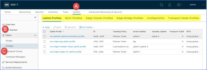
NSX-T Profiles
Profiles in NSX-T are very useful and are used to ensure consistent configurations are propagated to the transport nodes. Just another way NSX-T reduces configuration complexity during post deployment steps as you prepare the environment for NSX-T. There are various profiles that you can create from the NSX Manager UI. Each profile type and its used summarized below.
- Uplink Profile – defines how the uplinks for the transport nodes should be configured. Here you can configure how LAGs should be configure (if you plan on using them) along with the LACP mode, LACP Load Balancing method, number of uplinks (2 minimum) and LACP timeout options. ‘Teamings’ will define how you want your uplinks to behave by defining the Teaming Policy, Active Uplinks and Standby Uplinks.
- NIOC Profile – defines how to carve up bandwidth for the types of traffic. If you are familiar with how NIOC was configured on a vDS, this is really not that much different. You can specify different share values, impose limits (%) as well as reservations (%) which will guarantee specific bandwidth to traffic at all times.
- Edge Cluster Profiles – used to define how BFD (Bi-directional Forward Detection) will be applied on the Edge Cluster that services your environment. Here you can apply BFD Probe Internal (ms), PFD Allowed Hops, BFD Declare Dead Multiple and Standby Relocation Threshold (minutes).
- Edge Bridge Profile – describes how an Edge Cluster can provide Layer 2 bridging capabilities between NSX-T and a logical switch that is backed by a traditional VLAN.
- Transport Node Profile – this profile has everything including which Transport Zone(s) you want the Node Profile to apply to, how the N-VDS should be deployed as well as associate other profiles to the transport node including NIOC Profile, Uplink Profile, LLDP Profile and so on. Here you can also configure Network Mappings for Installation and Uninstall which is useful when migrating your existing networks over to the N-VDS (including pNIC migration).
You can locate the profiles in NSX-T from the NSX Manager UI by navigating to ‘System -> Fabric -> Profiles’ as seen below.
Conclusion
VMware NSX-T is true software-defined network (SDN) solution for customers looking to begin deploying and managing networks intuitively and programmatically. Literally start building and consuming network resources in your hybrid cloud (or on-premise data center). NSX-T 2.4 and 2.5 were both major ground breaking releases and widely viewed as the enterprise-ready SDN platform of choice. What would take some network teams several weeks to provision network resources in the past can now be done in a matter of minutes.
If you are planning on deploying Kubernetes (K8s) in your environment, NSX-T 2.5 with the NCP (NSX Container Plugin) provides integration with Kubernetes orchestrator; including CaaS/PaaS platforms such as PKS (Pivotal Container Service) and OpenShift. Start integrating more solutions by tying everything in vRealize Automation or IaC platforms such as Terraform and you have a very powerful holistic solution.
Lastly, NSX-T is a core part of VMware Cloud Foundation (VCF) which is simply a ‘cloud hypervisor’ solution that enables customers to leverage the VMware SDDC stack (vSphere, vSAN and NSX). VCF is simplest and most efficient path to the hybrid cloud and enables customers to have flexibility when choosing public cloud solutions (hint hint…don’t get stuck in a public cloud silo).
Stayed tuned for Part 2 of my NSX-T Deployment blog series where I will show you how to deploy/configure some of these components.
Useful Links
NSX-T Data Center Documentation
NSX-T Data Center REST API Guide
NSX Container Plug-in for K8s and Cloud Foundry
NSX-T 2.5 – What’s New for Kubernetes – blog article by Yasen Simeonov
VMware NSX-V vs NSX-T Comparison – by Brandon Lee (article is pre-NSX-T 2.5 release so be aware)
NSX-T 2.5 – A New Marker on the Innovation Timeline – by Umesh Mahajan

Great Article to explain to a beginner.
LikeLike
Great Article
LikeLike