Here I am going to walk you through the process of configuring Tier-0 ECMP in NSX-T. You should have a good understanding of NSX-T and it’s architecture as well as understand ECMP prior to starting.
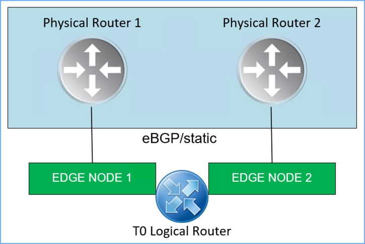
Before I begin let’s review real quick. ECMP is used to increase northbound/southbound communication bandwidth by adding multiple uplinks to the tier-0 logical router which is then configured by an admin for each Edge Node in an NSX edge cluster. These multiple ECMP paths serve multiple purposes including fault tolerance as well as load balancing of network traffic. In order for this to work properly, the tier-0 logical router must be in ‘active-active’ mode, and there is maximum of eight (8) paths supported. The diagram below is a basic illustration of two (2) NSX edge nodes with a single T0 Logical Router and the connectivity each Edge Node will have to the two separate physical routers.
NOTE: ECMP stands for Equal Cost Multi-path Routing Protocol but is not actually a routing protocol. It is a feature supported on a routing device.
Quick summary of features and support regarding ECMP in NSX-T 3.x:
- Maximum of eight (8) paths for Active/Active ECMP.
- The ECMP hash algorithm is 5-tuple northbound of Tier-0 SR (service router) based on:
- Source IP
- Destination IP
- Source port
- Destination port
- IP protocol
- Hashing algorithm determines how incoming traffic is forwarded to next-hop device where there are multiple paths.
- Prior to NSX-T 3.2, the hashing algorithm from DR (distributed router) to multiple SR’s (service routers) is 2-tuple and based on:
- Source IP
- Destination IP
- New to NSX-T 3.2, the hashing algorithm from DR to SR is now 5-tuple (ESXi and KVM) which allows for better distribution of traffic across all the available SR’s and based on:
- Source IP
- Destination IP
- Source Port
- Destination Port
- IP Protocol
- ECMP supports static routes, eBGP, iBGP as well as OSPF.
- The NSX-T 3.2 Release Notes can be found HERE and in the Useful Links section at the bottom of this blog.
An Edge Cluster is a logical grouping of Edge Transport Nodes which can be deployed as a VM or bare-metal edge. Scaling out from the logical networks to the Edge nodes is achieved by using ECMP. The environment I will be deploying in my lab is a multi-tiered topology with ECMP on Tier-0 which means I will have a Tier-0 logical router, a Tier-1 logical router and segments connected to T1.
You can read more about Edge Clusters, ECMP, and their supported topologies by referencing Section ‘4.10 Topology Consideration’ starting on Page 107 of the NSX-T Reference Design Guide 3.0 (PDF).
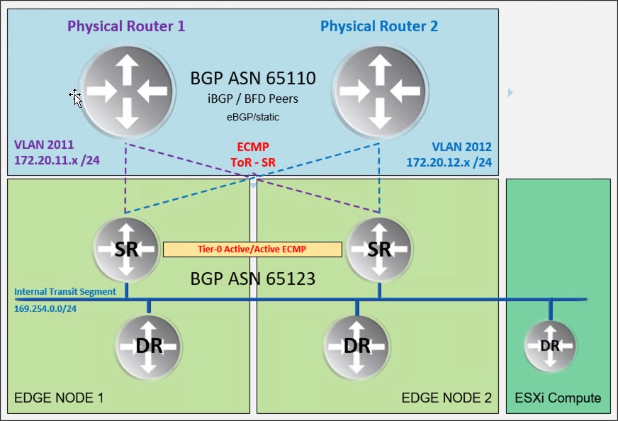
The image below is a logical topology of my NSX-T lab and can be used as a reference for what will be accomplished. I will configure eBGP between the T0 and the physical routers.
NSX-T PROFILES
Before we get into configuring ECMP on the T0 router, let’s review the current configuration in NSX Manager. Particularly the Transport Zones, Uplink Profiles, Transport Node Profiles and how the Edge Node VMs are deployed. This will help connect the dots as we proceed through the configuration. There are two separate clusters in the vSphere 7 environment; a compute cluster (3 ESXi hosts) and an edge cluster (2 ESXi hosts).
First let’s take a look at the Uplink Profiles. I have two (2) different profiles configured, one for the Compute/Host Overlay and the other for the Edge Nodes. There are two separate IP Pools created for the TEP segments; the Host Overlay Pool is on VLAN 121 and the Edge Pool is on VLAN 122. The Edge Profile team policy is set for ‘Load Balance Source’.


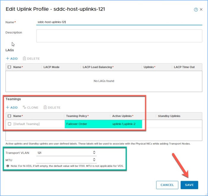
The Edge Uplink profile has two specific uplinks under ‘Teamings’ and named ‘trunk-a-2011’ and ‘trunk-b-2012’ respectively. I’ll make note of those uplink names because I need to add them to the configuration for my VLAN Transport Zone (below). These names will come up again when I create the uplink segments that the T0 will use to connect to the physical world in my SDDC.
NSX-T transport nodes
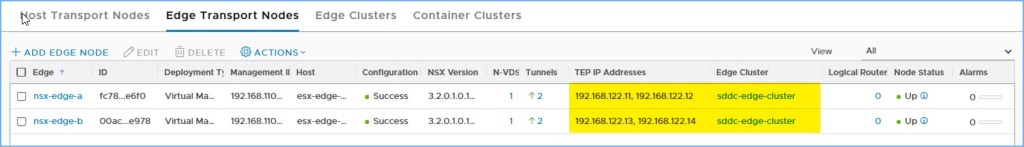
Next let’s take a look at how the Transport Nodes are configured, starting with the Edge Transport Nodes. When I deployed my Edge VMs you will notice I included both of the Transport Zones that I created for my SDDC, the Edge Uplink profile that I created above along with the IP Pool that I created (not pictured) and lastly the two distributed port groups on my vSphere Distributed Switch. These vDPG’s are configured for VLAN Trunking and will pass both my Uplink traffic to the physical routers (VLAN 2011 and 2012) as well as the TEP Pool for the Edge Nodes, in this case VLAN 122.
Next we have the Host Transport Nodes for my compute cluster. Here you will see I am using the VDS, the Overlay TZ, the host uplink profile profile that I created (above), the Host Overlay IP Pool and lastly the two uplinks I want to use. I then configured my compute cluster with this profile (2nd image below).
As you can see I am using NSX-T 3.2 in this lab 🙂
create nsx-t segments
Next I am going to create a couple NSX Segments to connect my Edge Nodes to the physical world. One segment will be for VLAN 2011 which will provide connectivity to Physical Router 1; the second segment will be for VLAN 2012 which will provide connectivity to Physical Router 2 (reference topology above).
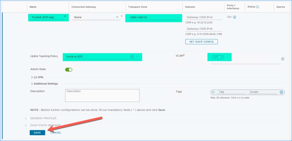
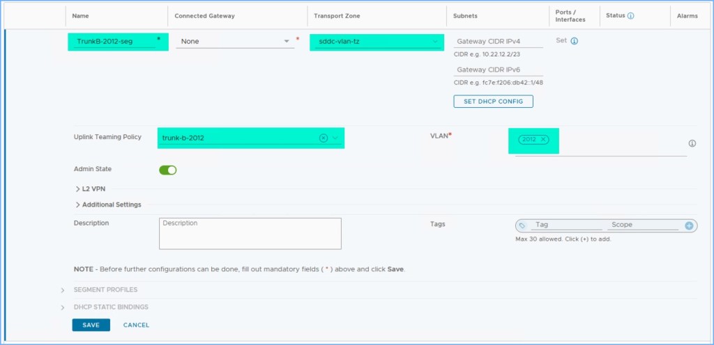

The only parameters on the segments that I configured is a Name, the VLAN transport zone, the Uplink Teaming Policy and the VLAN ID. As you can see for my ‘TrunkA-2011-seg’ I selected the VLAN TZ that I created, the team policy which is the uplinks I added to the VLAN TZ above and lastly the VLAN that connects to Physical Router 1. I repeat these steps for ‘TrunkB-2012-seg’ and verify everything is ready before proceeding to the next step.
deploy t0 router and configure interfaces
Now we are going to finally deploy the T0 router and configure the virtual interfaces that will provide the upstream connectivity to the physical routers. There will be a total of four (4) interfaces coming from the T0.
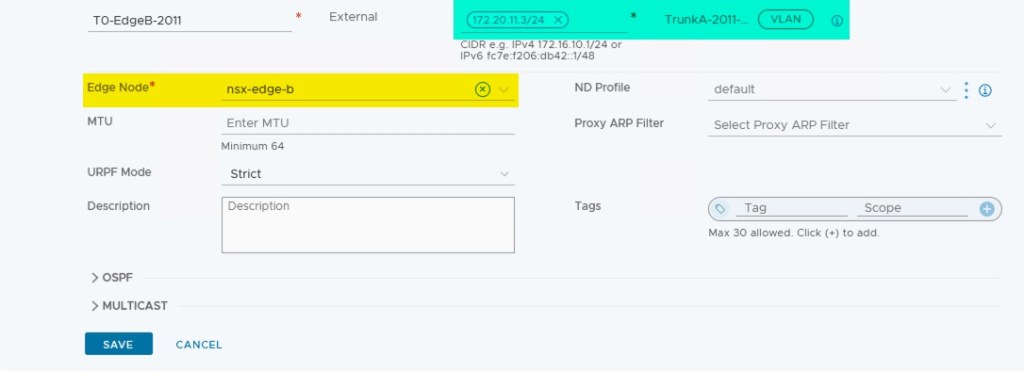
First I’m going to start with connecting Edge-A to segments 2011 and 2012 and configure them with a static IP address from each respective network.


Next I repeat this process for the two interfaces that will connect Edge-B to segments 2011 and 2012 and configure them with a static IP address.

Summary of the four (4) interfaces on my new T0 logical router.

tier-0 bgp configuration
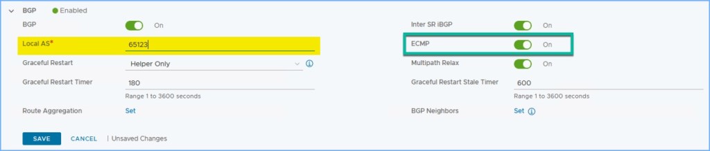
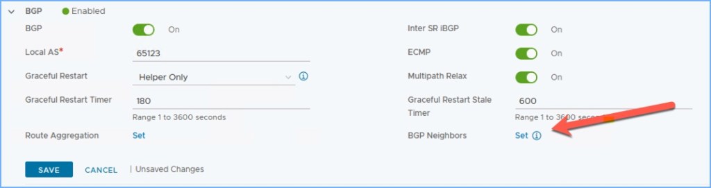
Now I am ready to configure BGP on my T0 logical router and create a BGP peering with my upstream physical routers. After configuring the interfaces, I scroll down and expand BGP. I enter the Local AS (ASN) that I will use on my T0, in this case 65123 and click Save. ECMP should be set to ON.
Then click on ‘Set’ next to BGP neighbors to begin adding the two (2) upstream BGP neighbors, in this case the physical routers.
First I add the BGP neighbor for Physical Router 1 (PR1). The IP address of the interface on PR1 is 172.20.11.1 which is on the VLAN 2011 network in my lab. I enter the IP address of the neighbor and then select the two (2) source addresses from my T0 router on the same IP segment. In this case, I select 172.20.11.2 and 172.20.11.3 which I created a moment ago. Click Save.

I then my second BGP neighbor, this time for Physical Router (PR2). The address of the interface on PR2 is 172.20.12.1 which is on the VLAN 2012 network in my lab. I enter the IP address of the neighbor and then select the two (2) source addresses from my T0 router on the same IP segment. In this case, I select 172.20.12.2 and 172.20.12.3 which was created a moment ago. Click Save.

Wait a few moments for the neighbor adjacencies to form; refresh the screen a few times if needed. The BGP neighbors should indicate SUCCESS in the Status column.

Next, don’t forget to set Route Redistribution for the T0 router to communicate and re-route segments to the upstream physical routers (below). My next step will be to deploy a Tier-1 router and attach a few segments to the T1 which will need to communicate upstream in my SDDC.

Before I deploy my T1 router and a few segments, I will verify my BGP peering with my upstream routers.
verify t0 bgp
Connect to the Edge Nodes using SSH and execute the following commands to begin verifying the BGP peers from the command-line. Just an extra step that I like to do using the CLI. In step 2 below I select ‘vrf 1’ because that is the Service Router.
- get logical-routers
- vrf 1
- get bgp neighbor summary
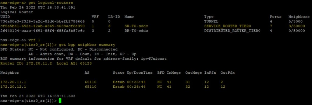
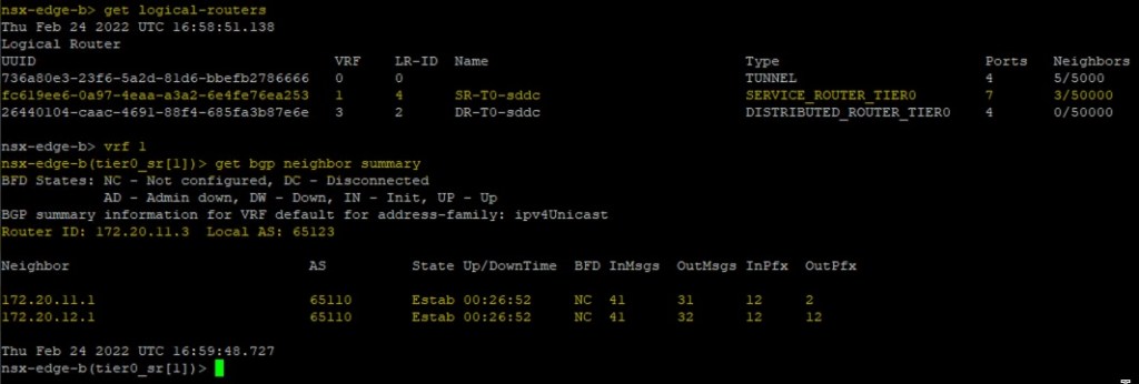
You will see my BGP neighbors are both Established and online.
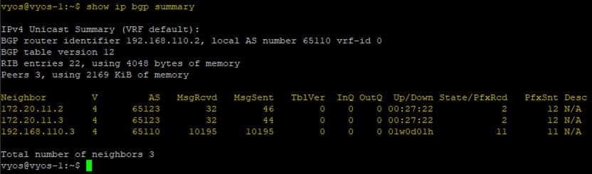
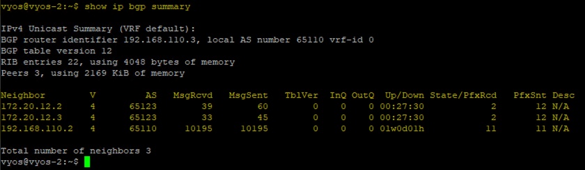
Next I connect to my VyOS routers in my lab and execute a few commands to verify the BGP adjacency from their perspective.
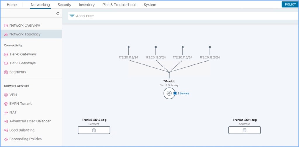
And you can also see from NSX Manager the topology from my T0 router. There are four (4) paths from my ‘T0-sddc’ router upstream to my physical world.
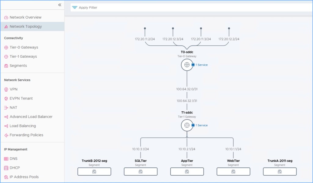
deploy tier-1 and some segments
I’m not going to go into tremendous detail but next I deploy a Tier-1 logical router and attach a few segments to the new T1 (below). The T1 connects to the T0 that I just created above and the transit networks are automatically established. Don’t forget to enable route redistribution on the T1 before proceeding (Route Advertisement on T1 gateway).

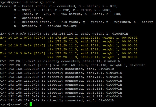
From an SSH terminal to my NSX Edge Nodes and my VyOS routers, I execute a few commands to view the routes to the new NSX segments being advertised.
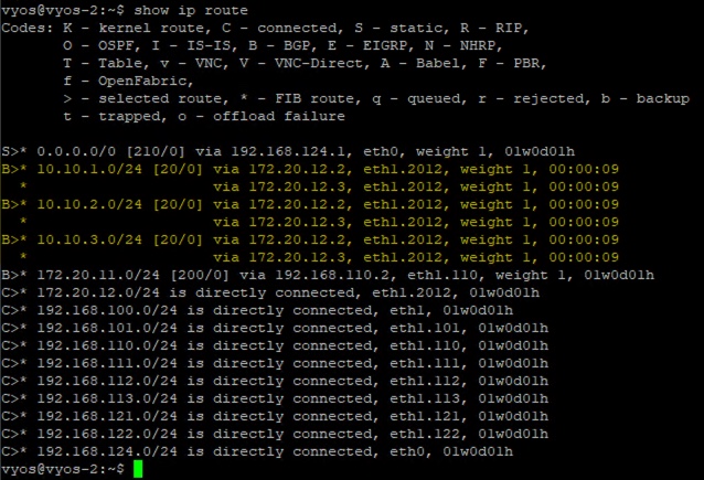
From my VyOS routers (PR1 and PR2) I execute the ‘show ip route’ command. As you can see the network segments I created a moment ago have two paths each coming from each Edge Node; four (4) paths total.
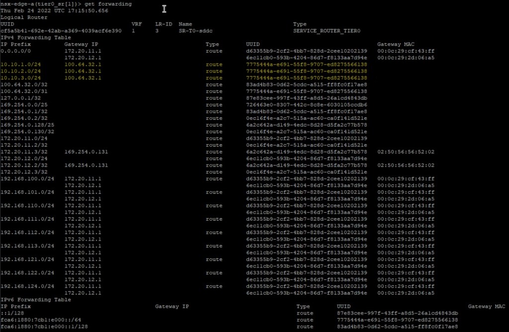
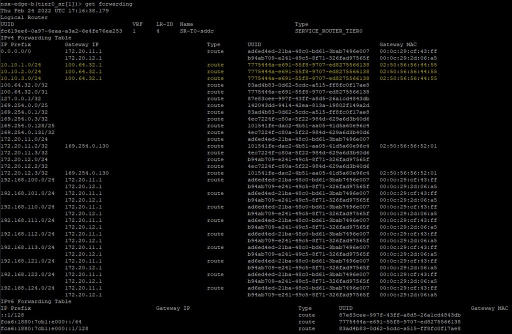
From the NSX Edge Nodes I execute the command ‘get forwarding’ to see the routing tables.
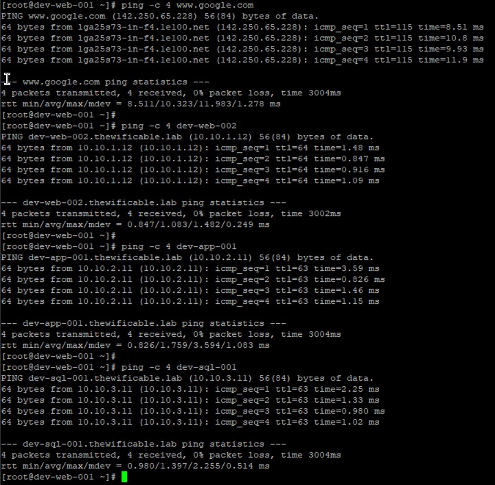
I also power up the VMs connected to my new NSX segments. Execute a few ping commands to test connectivity to VMs connected to the other segments as well as the public internet. I have successful connectivity!
And that is all there is to it. Fairly easy T0 ECMP configuration in my home lab. There are some great resources out there from VMware as well as other blog articles who go a bit deeper than I did above.
useful links
Understanding ECMP Routing (NSX-T Data Center Online Documentation)
NSX-T Data Center 3.2 Release Notes

Awesome article!!!
LikeLike
Since NSX-T 3.2, ESXi uses a 5 tuples algorithm to load balance the traffic from the DR to the SR 🙂
LikeLiked by 1 person
Good call out. I’ll clear that up and specify that prior to NSX-T 3.2, 5-tuple algorithm only existing northbound from SR whereas 2-tuple was between DR and SR. New to 3.2, 5-tuple now exists between SR and DR which allows for better distribution of traffic across all the available SR’s.
LikeLike
ECMP supports static routes, eBGP, and iBGP. => and OSPF 🙂
LikeLiked by 1 person
Yes, that is correct. Thank you for correcting me there. My brain sometimes forgets that OSPF is now in NSX-T. Correct me if I’m wrong but that was introduced in 3.1.1.
LikeLike
Is it necessary to have the Gateway FW disabled to use ECMP?
LikeLike
That is correct. No firewall on the T0 router when using ECMP. Disable it.
LikeLike
Thanks for confirming. I was struggling to find anything definite in the documentation.
LikeLiked by 1 person