In this article I am going to take you through the steps for deploying the AVI controller and integrating it with VMware vCenter Server 7.0. If you are new to AVI Vantage, it is a software-based solution that can provide analytics in real-time as well as elastic application delivery services. I am a big fan of AVI due to it’s multi-cloud capabilities and it’s ability to bring flexible load balancing to today’s modern VMware-based hybrid cloud data centers.
On a daily basis, I come across IT teams lacking agile application networking services; their inability to meet their network automation and self-service goals and continue to invest in legacy technology that simply increases complexity. The AVI platform uses a distributed architecture that manages a distributed fabric of AVI Service Engines (SE). It can be deployed on bare metal or as a VM on commodity x86. In my opinion it is a game changer that helps customers respond quickly to business needs by becoming more agile and accelerate the journey to cloud.
I really like the documentation pages for AVI. Everything from Architecture, Installation Guides, Configuration Guides, Operations, Scripting…you name it. It is on the website. I find it easy to follow and use. I’m specifically focusing on installation and some configuration in this article. If you navigate through the docs page under ‘Guides -> Installation’ you will see a wide variety of deployment options.
I am deploying AVI and integrating with my VMware vCenter Server so I can eventually enable Tanzu on the compute cluster in my nested lab. I highly advise testing on your own in an isolated lab environment and not in a production data center.
AVI Brief Overview
Before we get into it, here is some important things to consider when integrating AVI with your on-premises vCenter Server.
The AVI Controller is the ‘control plane’ that is responsible for storing and managing all policies related to management and services. Once AVI is integrated with vCenter, it discovers the inventory including data centers, hosts, networks and VMs. This information is auto-discovered which enables virtual services to be created/added using the web UI. By default the AVI controller is deployed as a single VM and can be scaled to a 3-node HA cluster containing 3 controllers.
The AVI Service Engines (SE) are the ‘data plane’ and also run on separate VMs. These SE’s are the components that provide several key functions including:
- Collecting real-time end-to-end metrics for network traffic between apps and end-users.
- Provide application delivery services to end-user traffic.
Before you deploy you should be aware of the VM minimum hardware requirements to install both the controllers and the SEs. You need to make sure that the ESXi hosts in your cluster have the required physical resources to ensure uptime and performance. For optimal performance the VMs should be deployed with CPU and memory reservations and a thick provisioned disk. The minimum hardware requirements for the two VMs are summarized below.
- AVI Controller: 8 vCPU, 24 GB memory, 128 GB disk space
- AVI SE: 1 vCPU, 2 GB memory, 15 GB disk space
The HA controller deployment requires (3) controllers for a fully redundant cluster and per best practices each controller should run on a separate ESXi host. The number of SE’s depends on the number of applications that AVI will serve. Again, resources reservations are preferred but not required.
When it comes to the networking requirements, the AVI controller requires one (1) management IP address; this IP is used for running administrative commands as well as for the controller to communicate with the SE’s. The IP addresses in a 3-node HA controller cluster should all belong to the same IP range (subnet). Refer to the Controller Cluster IP doc from AVI for more info. It is recommended to use a static IP for the controller IP. If you want to use DHCP, make sure you can use a DHCP reservation so it can preserve that DHCP allocated address constantly.
As for the AVI SE’s, those VMs require a management IP address, a VIP address and a third address that faces a pool network. For fast deployment, the recommendation is to use DHCP over a static assignment for the SE management and pool network allocation.
Last thing before we start deployment is understanding the different modes of deployment. There are three (3) modes available.
- Write Access Mode is the recommended option for deployment. Using this mode requires the use of a vCenter user account with write privileges. With this mode, the AVI controller automatically deploys AVI SE’s (as needed) and then discovers information about the environment.
- Read Access Mode requires the use of a vCenter user account with read privileges. The controller accesses vCenter to discover inventory info about the VMs and networks; the SE’s are also turned on and connected to their networks.
- No Access Mode means the AVI controllers does not access vCenter at all. This means the AVI and vCenter Server administrator must deploy the AVI SE’s manually as well as determine networks, interface IPs and map the SE to the correct corresponding networks. To put it simple, it is more manual work.
AVI OVA Deployment
Deploying the AVI OVA is as simple as deploying any other OVA. Virtual appliances are a beautiful thing and typically very easy to deploy. If you are deploying AVI then you are already experienced with deploying virtual appliances. Just a few quick easy steps. The specific version I am deploying AVI 21.1.3; my vCenter and vSphere environment is vSphere 7.0 U2.
Prior to deployment I have several virtual networks on my vSphere Distributed Switch (vDS) that I am going to use during my AVI deployment and configuration. In my nested home lab, I have a default management network, a default workload network and another network that will be my AVI Frontend network. Summary of my networks below.

- Deploy the OVF Template from the vSphere Client.
- Carefully follow the Deployment Wizard step-by-step. Review the resources, remember to use Thick Provision Lazy Zeroed for the virtual disk format (recommended for optimal performance), specify the management network for the controller and enter the static IP information. NOTE: If you are performing a POC or in a test environment as I am with my home lab you can use a thin provisioned disk (7.9 GB thin provisioned).
- Once the OVA is deployed into your vSphere inventory, power on the VM.
- OVA Deployment is complete.
AVI Controller Setup
Next comes the AVI controller setup. After the appliance is deployed and powered on, wait approximately 5-10 minutes before opening your browser to the management IP that you assigned to the controller during OVA deployment.
1. When you first connect to the AVI controller URL, you must login with the ‘admin’ account and specify a secure password. The passphrase is for configuration export and periodic backup. Click ‘Create Account’ to proceed.

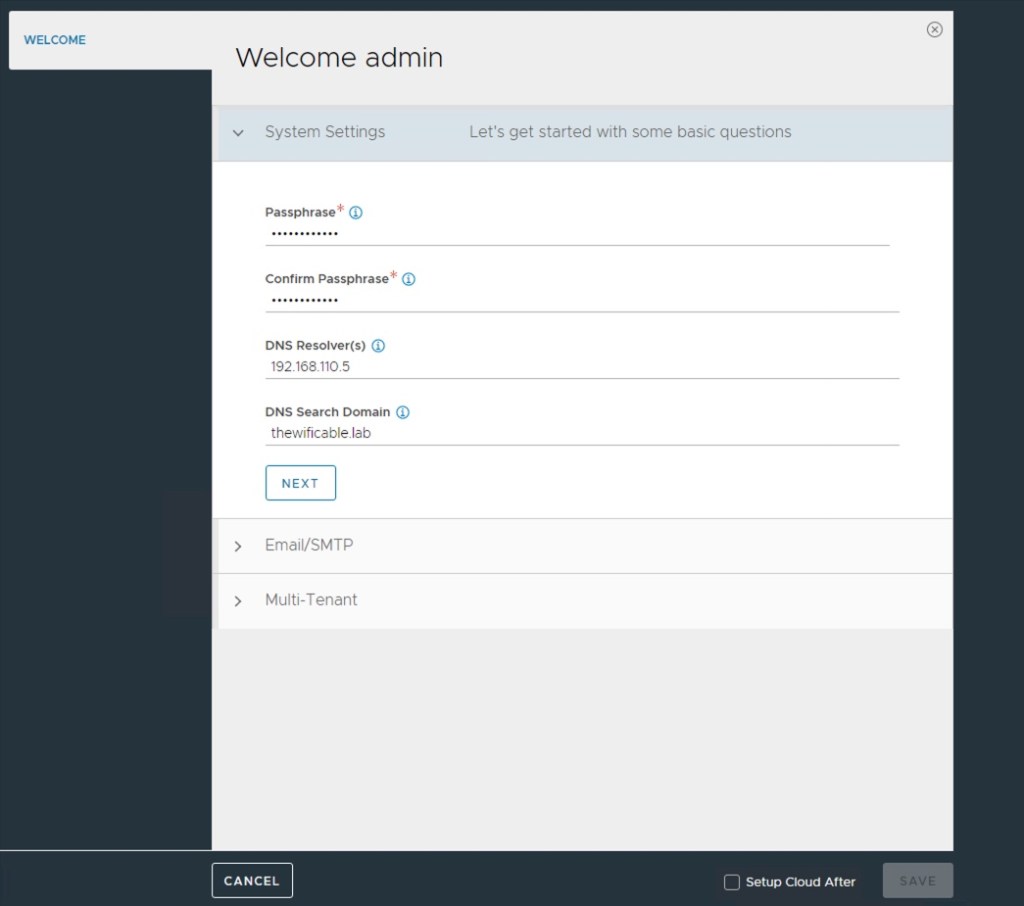
2. Next a ‘Welcome’ screen will appear prompting for more information including passphrase, DNS resolve and search domain. Enter the info and click Next.
3. Enter Email/SMTP info; there are 4 options to choose from and can be changed later. Click Next.

4. The third section is the Multi-Tenant settings. I’m going to leave the defaults for now. If you hover the cursor of the ‘information’ icon you will see a description which I have summarized below for you. Select the box that says ‘Setup Cloud After’ and then click the green SAVE button when you are ready to proceed.
IP Route Domain – When ‘Per Tenant IP Domain’ is selected, each tenant gets its own routing domain that is not shared with any other tenant. When ‘Share IP Domain across all tenants’ is selected, all tenants share the same routing domain.
Service Engines are managed within the – Controls the ownership of Service Engines. Service Engines can either be exclusively owned by each tenant or owned by the administrator and shared by all tenants. When Service Engines are owned by the administrator, each tenant can have either read access or no access to their Service Engines.

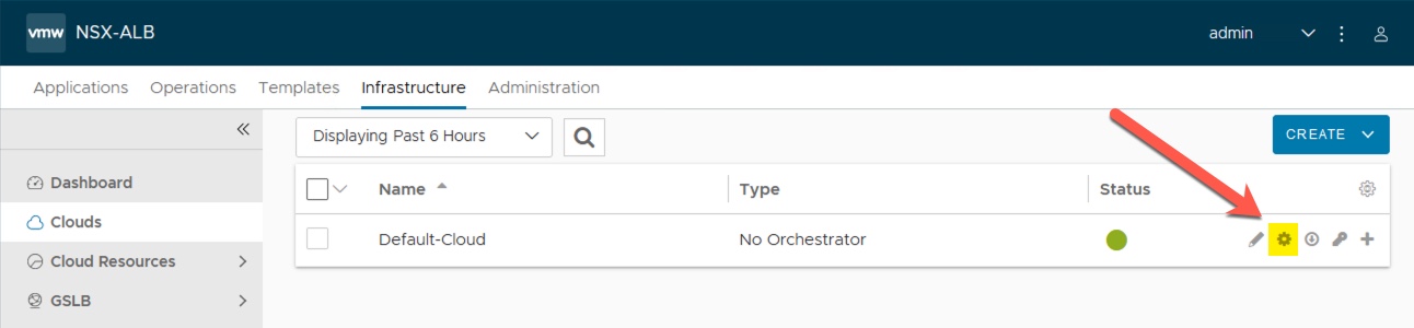
5. Next I will be taken to the ‘Infrastructure – Clouds’ section of the UI. You will see the ‘Default-Cloud’ listed with ‘No Orchestrator’ and a few icons to the right next to the Status column. Click on the small gear icon. The ‘Convert Cloud Type’ window will appear. I select the drop-down menu and choose the vCenter option and then click Yes, Continue.
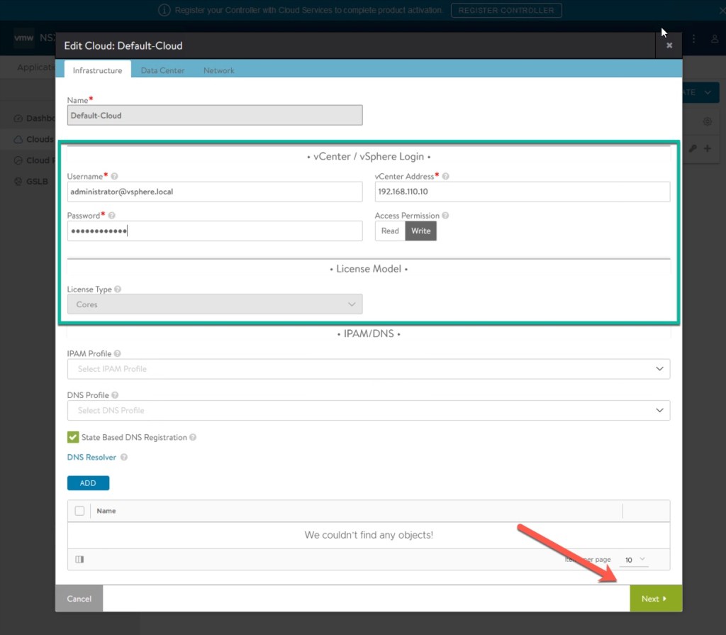
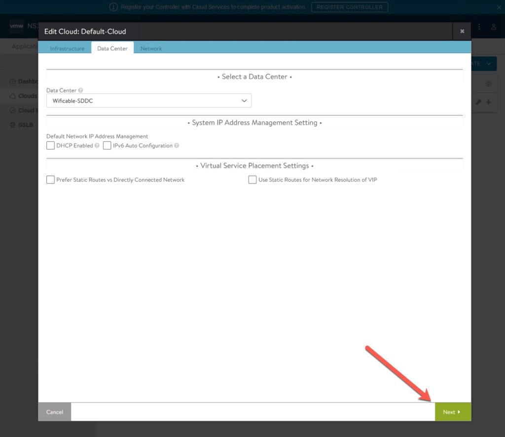
6. The ‘Edit Cloud: Default-Cloud’ window will appear with 3 tabs at the top starting with Infrastructure. Enter the username, password and IP address of the vCenter Server. Click Next to proceed to the Data Center tab. Review the information on the Data Center tab, leave the defaults and click Next.
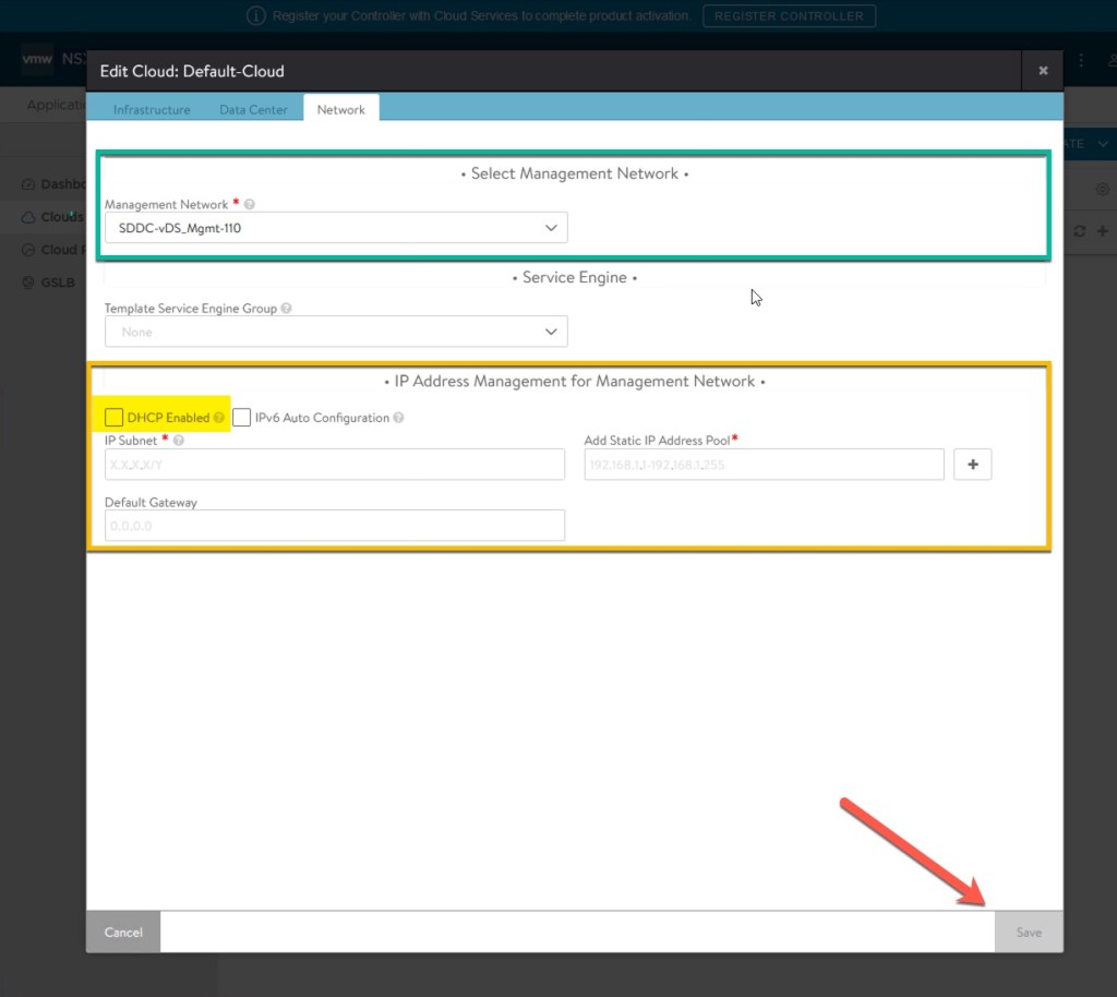
7. On the Network tab select the Management Network from the drop down menu. This is my default management network in my lab where vCenter, ESXi and the where my newly deployed AVI Controller is connected. My management network has a DHCP server so I am selecting the ‘DHCP Enabled’ option and click Save. If you do not have DHCP on your management network you need to specify the subnet ID in CIDR format, specify an available range of IP’s from your management network and then the default gateway before you click Save. You will then return to the ‘Default-Cloud’ and the Status should have a Green dot before proceeding to the next step.
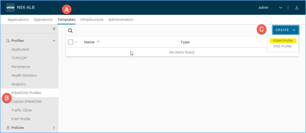
8. Next I need to create an IPAM/DNS profile. Navigate to the ‘Templates – Profiles’ section of the UI, select ‘IPAM/DNS Profiles’ and then click Create IPAM Profile.
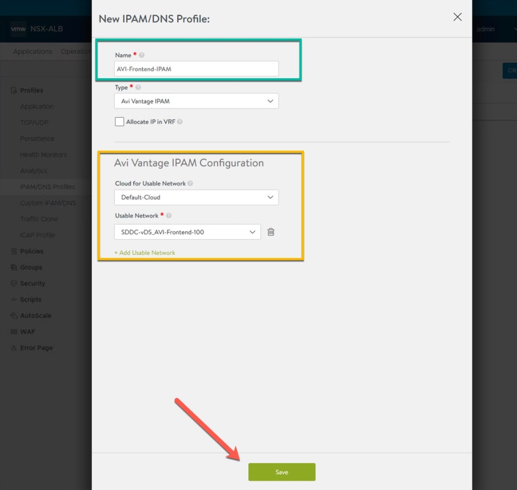
9. Specify a name for the IPAM profile. Select ‘Add Useable Network’. I select my ‘Default-Cloud’ and then choose the AVI Frontend dvPG that is on my vDS. Click Save.
10. Now that the profile is created, I need to add it to the Default-Cloud configuration. Navigate to ‘Infrastructure – Cloud’ and click the Edit icon next to the Default-Cloud.

11. In the Edit Cloud dialog box, I select the new IPAM profile that I just created from the drop-down menu and click Save.

12. Next we need to apply some network settings for the AVI Frontend segment. Navigate the AVI UI to ‘Infrastructure – Cloud Resources’ and then select Networks. Locate the Frontend network segment, in this case my AVI Frontend dvPG and click the Edit icon.
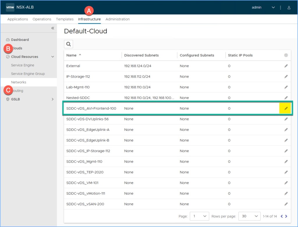
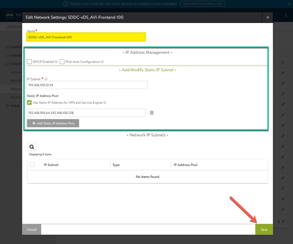
13. The ‘Edit Network Settings’ dialog box will appear for the network. Under ‘IP Address Management’ you have an option of selecting ‘DHCP Enabled’ if in fact you have DHCP enabled for that segment. If you are not using DHCP, click the ‘Add Subnet’ button on the right. Specify the CIDR format of the frontend network. Then select ‘Add Static IP Address Pool’. The segment can be used in one of two ways depending on how your infrastructure is designed. If the VIPs and SEs will be deployed on the same segment/subnet, check the box for ‘Use Static IP Address for VIPs and Service Engine’. If you do not check this box, then the assumption is the VIPs and SEs are on separate network segments and therefore you must specify them by using the ‘Use for VIPs’ and ‘Use for Service Engines’ options. I’m using a single segment for both in my lab and need to specify a range on the subnet to use as seen below. Click Save twice and return to the Default-Cloud Networks summary.
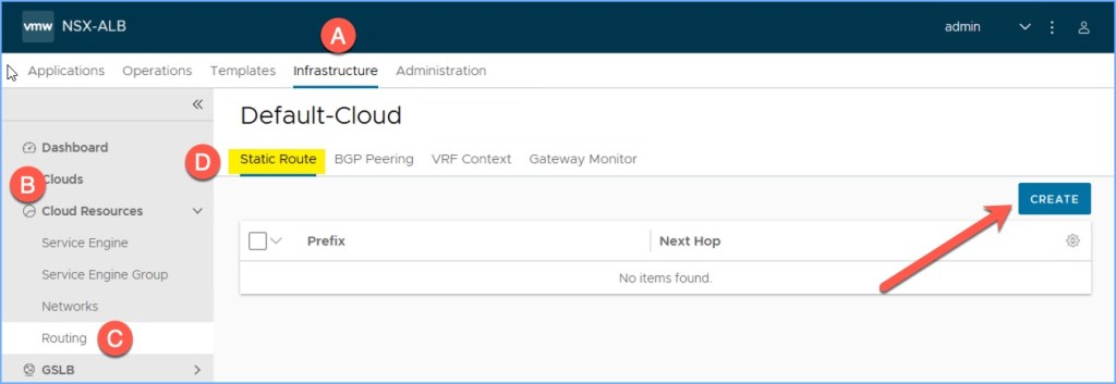
14. Next I am going to create a static route from my Workload Network (192.168.101.x /24) to the next hop address gateway IP for my Frontend segment, 192.168.100.1. Click on the ‘Routing’ option under Cloud Resources and click the Create button.
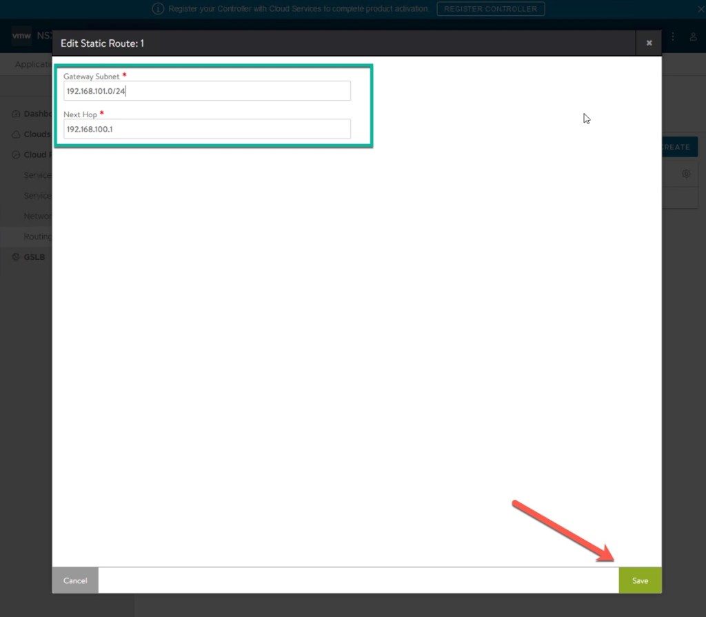
15. Enter the Static Route information for workload network to reach the gateway for the Frontend segment. Click Save.
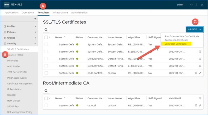
16. Next I am going to generate a self-signed SSL/TLS controller certificate. In the AVI UI, navigate to ‘Templates – Security’ and then select ‘SSL/TLS Certificates. Click the Create drop-down menu on the right and select ‘Controller Certificate’ from the listed options.
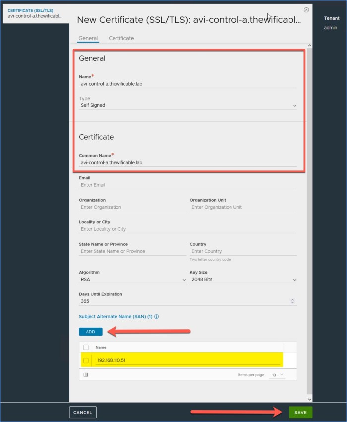
17. In the ‘New Certificate (SSL/TLS)’ window, enter the name for the certificate, select Self Signed for the Type and enter a Common Name. I used the FQDN for the AVI controller for the name and CN. I then click ‘Add’ for the Subject Alternate Name (SAN) and enter the IP address of my controller and then click ‘Save’ when I am finished.
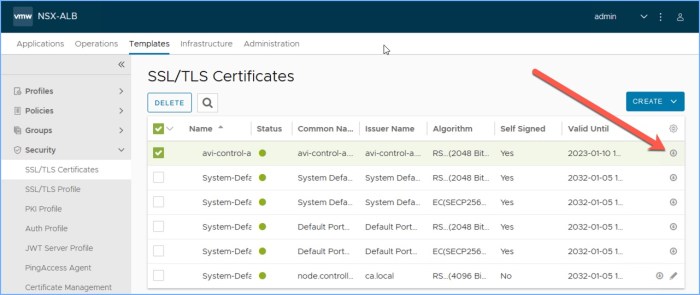
18. I then return to the list of SSL/TLS Certificates and click the small download icon next to the certificate I just created for the controller.
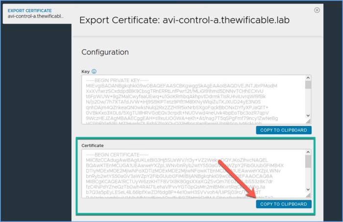
19. In the ‘Export Certificate’ window for the self-signed controller cert, click Copy To Clipboard below Certificate (not the Private Key thumbprint). Past the Certificate Thumbprint in a word editor (Notepad, Notepad++, other). Click Done when finished.
20. Next I need to configure the controller to use the new self-signed certificate. Navigate to ‘Administration – Settings’ and then select ‘Access Settings’ and lastly the Edit icon at the top-right.

21. Clear out the existing SSL/TLS Certificates under the ‘System Access Settings’ and from the drop-down menu select the newly generated certificate. Click Save.

22. Last but not least, don’t forget to apply your license! 🙂
Enable Tanzu using Workload Management
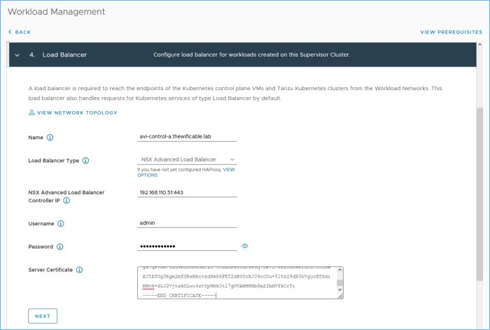
Now that AVI is deployed and configured, it is ready for Tanzu! You should be familiar with this process before proceeding. I am not going to walk through enabling Tanzu but I will highlight ‘Step 4 – Load Balancer’ section of the enablement process where I will specify my AVI load balancer. The certificate thumbprint that was copied in Step 19 above will be used during this step.
Enter the information for the AVI load balancer:
- DNS compliant name (FQDN).
- NSX Advanced Load Balancer for type.
- NSX Advanced Load Balancer Controller IP
- Username and password for the controller.
- Copy and paste the certificate thumbprint.
Once you complete the process of enabling Tanzu, follow the remaining steps including creating your first Namespace, apply permissions, storage, limits, VM classes, download the CLI tools and so on. Once you have a simple TKG deployment online (control plane + worker nodes) you can then deploy some workloads that will use the load balancer (i.e. NGINX is a popular one that I have seen in several labs).
Another thing to watch for as the Tanzu Supervisor Cluster comes online, you will see the AVI SE appliances deploy and appear in the vSphere inventory (below). Monitor this progress and watch for any errors.

Useful Links
Here are some useful links to help you. These links are provided by the OEM.
VMware NSX Load Balancer Product Homepage
Integrating with VMware vCenter Server Solution Brief (PDF)
Installing AVI Vantage for VMware vCenter for version 21.1 (AVI online docs)
VMware NSX Advanced Load Balancer and NSX Integration (Solution Overview)
