Let’s face facts, automation makes our lives easier! Technology has quickly become more and more complex over the last 10 years and demand is increasing every day. Agility is very important to organizations that want to remain competitive. The business needs to respond FAST to an opportunity or even a threat. Fast IT must be able to deliver effectively and efficiently around the clock. The alignment between the business and the IT that supports the business equates to a high demand for agility. Powerful new technology will empower business to quickly make changes, adjust processes and so on without relying on expensive time consuming IT projects to support it.
VMware vRealize Automation and VMware NSX are just two components that fit the bill when it comes to creating a more agile infrastructure to support any line of business. The combination of the two solutions provides the ability to quickly provision and fully configure resources at the click of a button. Together they optimize IT processes which positions the business to transform and become more innovative than ever before. Becoming agile is somewhat of an IT excursion, a journey, and vRA and NSX are just two solutions from VMware to help you get there.
You should be very familiar with vSphere, NSX and vRealize Automation to accomplish the tasks that I will be covering. You should already know how to provision and configure NSX resources such as Logical Switches, Routing, DFW Rules and other advanced security settings. You should also be familiar common vRA tasks and so on including blueprint design, endpoint configuration and custom catalog design.
vRA and NSX Together
Let’s briefly talk about these two solutions. vRA supports NSX virtualized networks and this also applies to Integrated Container Networks for vRA. In vRA, an IaaS admin must create endpoints to integrate it with various external endpoints. In this blog, vSphere and NSX endpoints will be our primary focus.
This is accomplished from the Infrastructure > Endpoints > Endpoints location within the vRA interface as you see below. So make sure you have the external configuration parameters configured properly before proceeding. Reference online documentation from VMware to assist with this. As you can see I have my vRA configured with a few endpoints including NSX and vCenter. I also have vCO and vROPs.

Once you have this part complete and your environment is inventoried by vRA you can start designing your vRA blueprints with NSX components immediately.
Next thing you want to do is create some Network Profiles in vRA which map to how you want to use NSX. The network profiles can be one of three (3) types:
- External
- Routed
- NAT
We are going to work with the External and Routed (On-Demand) network components in our blueprints. I’ll save the NAT component for another day. Using an External Network component means you want to map a network in a blueprint to an existing NSX network that has been already provisioned and in use. This NSX network is simply an existing NSX logical switch in your existing NSX infrastructure.
For example, I have three (3) networks provisioned for my 3-tier TPS application in my ‘initech.local’ infrastructure. I don’t want to get rid of them just because I deployed vRA and re-architect my entire NSX environment. I want to continue using those networks and now I want to automate the provisioning of resources. Everything I have in place needs to remain and simply want to utilize vRA to handle all deployment and configuration.
My blueprint (aka workflow) will basically be configured to connect the vRA provisioned machines to an existing network segment and that’s it. No NSX resources will be deployed for these specific workflows.
But I can also design my blueprints to use something called an On-Demand Network. This means my NSX network resources are provisioned when I deploy my virtual machines from vRA. They all become bundled as one big workflow. Very useful when you need to plan for something that needs to be a little more “elastic” when it comes to deployment and removal; or for organizations who need to scale quickly! Everything gets provisioned together and when I am finished with those resources I can have everything removed. Great solution for organizations with elastic requirements.
So how do I align this with the business? Once I figure out ‘how the business?’ plans on using the resource(s) they want provisioned I can then decide whether this needs to be more static or elastic by design. For a static environment I would have all of the necessary NSX resources in place…ESG, DLR, Logical Switches, Security Groups, etc. then design my blueprints to simply deploy VMs into the environment and consume those existing resources. The blueprint will be simple…deploy VM(s), attach to existing resources based on a vRA reservation, run a few ‘in-guest scripts’ to customize the user experience per business requirements and ‘ta-da’…everything is complete!
Now lets say the business wants to expand capacity (workloads) during ‘peak times of business’ and those workloads need to be removed after that peak interval. Could I attach those resources to the existing NSX resources as I stated in the previous paragraph? Sure! Just be sure to plan for that expansion ahead of time.
What if you don’t want to worry about under-planning or over-planning for that and simply want to provision everything all at once and remove it when you are finished? That’s where the ‘On-Demand’ portion of the networking comes into play. I can create a ‘Routed’ network profile in vRA and generate network ranges to support the infrastructure that I plan to deploy.
One example for the elastic approach is for environments where a lot of testing is required. Once the end users are finished with testing or whatever tasks they need to do, the resources can all be removed entirely (VMs, networks, etc.).
In environments where I need more of a ‘constant’ I will lean more towards deploying everything I need in NSX ahead of time and then design my blueprints to use these existing networks. This also means my blueprints will require less in their workflows because they’ll simply be designed to deploy the VM(s) and perhaps configure those VMs with specific security settings (NSX security group, NSX security policy, security tag, etc.).
To quickly summarize…what’s the difference between my ‘External’ and ‘Routed’ network profiles in vRA?
External maps to an already existing network resource; a pre-configured TCP/IP segment. This segment can be an existing port group or an NSX logical switch. vRA will not deploy network resources or other components. It can also be a port group a Distributed Switch.
Routed is an ‘On-demand’ type of network resource; requires a bit more collaboration between the VM admins and Network Admins when planning the network segment they want to use for provisioning network resources that will service the VM workloads. All VMs and network resources are deployed by the vRA blueprint.
Create a Network Profile for Existing Network
Here is a step-by-step procedure for creating a Network Profile in vRA 7.3 and mapping it to an existing NSX logical switch. My existing NSX environment has three (3) logical switches for my 3-tier application.
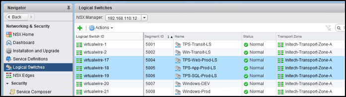
The TCP/IP network segments are configured with the following IP ranges:
- TPS-Web-Prod-LS: 10.10.10.0 /24
- TPS-App-Prod-LS: 10.10.11.0 /24
- TPS-SQL-Prod-LS: 10.10.12.0 /24
Next let’s log into vRA and create these profiles for these networks.
- Log into vRA and navigate to Infrastructure > Reservations > Network Profiles.
- Click the ‘New’ drop-down menu and select External.

- Enter the General information required for this network segment. Here I have entered a Name, selected a subnet mask and provided a Gateway. I’m also utilize vRA IPAM to manage the IP address allocation for my network.

- Select the DNS tab and enter your DNS information. Then select the Network Ranges tab and click on New. Enter a name for the range and then enter the Start and End IP addresses for your range. I’ve excluded gateway from my range.

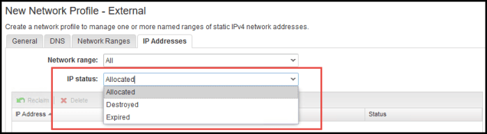
- Select the IP Addresses tab. This range will remain empty when you first configure the profile because nothing has been allocated yet. Once you have provisioned VMs the addresses that are ‘in use’ will appear here. Admins can reclaim the IP addresses as needed. If you select the drop down menu for ‘IP status’ you will find three options ‘Allocated, Destroyed or Expired’ to filter the list.
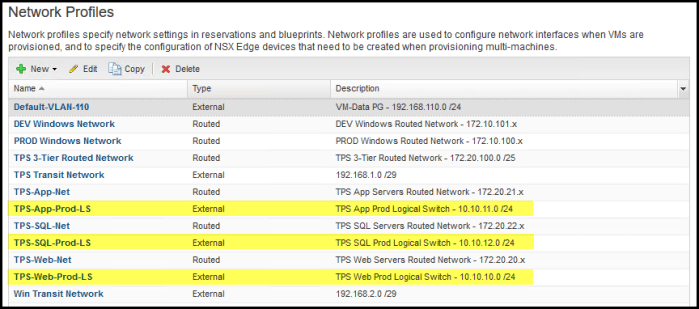
- Click Apply and OK and the new Network Profile will be added to my list of profiles. I repeat the steps above to create the remaining two network profiles for my other segment (logical switches). My three (3) external network profiles are now created.
- This completes the steps required to create a network profile for an External network to be used by vRA and NSX.
Create a Network Profile for On-Demand Routed Network
Here is a step-by-step procedure for creating an ‘Routed’ Network Profile in vRA 7.3. This type of network is an ‘On-Demand’ type of network resource that is provisioned along with other resources in a vRA blueprint. So an X number of VMs is being provisioned from your blueprint and you want the network resources to be provisioned with them VMs and later connect the VMs to this network.
Before you proceed create another external network profile for your Transit Network. The transit network range for my TPS application is my 192.168.1.0 /29 network. So again, repeat the steps above for the External network profile for your transit network; you will need this in a moment.
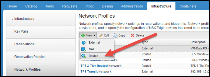
- Log into vRA and navigate to Infrastructure > Reservations > Network Profiles.
- Click the ‘New’ drop-down menu and select Routed.
- On the General tab I enter some information about my routed network including the Name, External Network Profile, Subnet Mask, Range Subnet Mask and Base IP. Click the DNS tab.

- Enter the information for DNS and then select the Network Ranges tab. On the network ranges tab select the Generate Ranges button and observe the ranges that are quickly created for your routed network profile. Click Apply and OK.
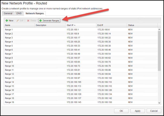
- That completes the process of creating a network profile for an On-Demand Routed network for vRA and NSX.
Security Group Automation
Automating security groups is initially managed from the Networking & Security console in your vSphere Web Client. The only thing you need to accomplish from the vRA perspective is make sure the data collection (inventory) is performed vRA on the NSX and vSphere endpoints.
This simply means is you need to create some Security Groups and/or Security Policies using the NSX Service Composer. You then allow vRA to execute a data collection against your environment. The collection interval you have for your environment can be automated or you can force a manual collection by selecting Request Now from the Data Collection section of your Compute Resources in vRA.
Here is a summary of the Security Groups that I have configured for my environment. I have six (6) security groups configured; all with Dynamic Group Membership based on the name of the VM (naming convention). I like using this option because it enables to me to be both consistent and easily align my provisioned resources with the proper machine prefixes that I define in vRA.
The Security Groups that have the ‘vRA’ prefix will be used later during a specific blueprint design task where I will utilize NSX Security Policies via On-Demand Security Groups in vRA.
TIP: The machine prefix that you configure in vRA should also be set on your Security Groups that are configured to use a dynamic group membership. Easily aligns the two!

The only reason why I have two separate groups for each machine type is during one vRA deployment I will use Existing networks in my vRA blueprint that map to existing NSX logical switches; then in the other blueprint I plan on using my On-Demand Routed network. I want different naming conventions for each so I can easily differentiate which type of network my VM is connected to just be looking at the name of that VM.
Next let’s take a glimpse of my two Security Policies that I have configured in NSX. One for the web servers and one for my SQL servers.
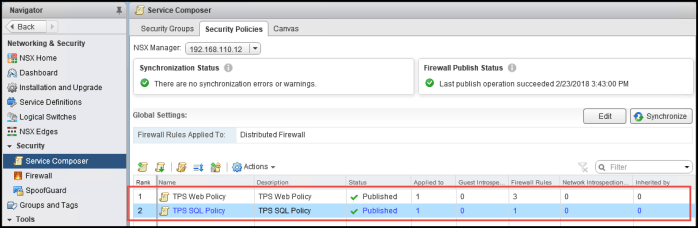
NOTE: If you just created your Security Groups or Policies in NSX then you will need to execute a manual data collection within vRA.
vRA Blueprint with External Networks and Security Groups
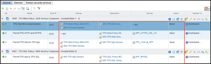
Now we are going to create a multi-machine vRA blueprint that will provision machines that will connect to existing NSX resources and also inherit existing pre-defined NSX firewall rules. Let’s get a glimpse of the firewall rules that I have created. My goal will be applying these rules automatically to my new VMs when they are provisioned by vRA.

Just four (4) simple rules that will do the following (and I will be using the new NSX 6.4 Layer-7 services for my firewall rules). All source and destination will be set to use user defined Security Groups. Here is a brief summary of the config pictured above:
- Permit TPS App to TPS SQL for the APP_MYSQL service.
- Permit TPS Web to TPS App for the customized TPS_Tomcat_APP.
- Permit ANY to the TPS Web for APP_HTTPS_SSL_V3.
- TPS Web Micro-segmentation to the TPS Web Servers to BLOCK all communication with one another.
GOAL: The blueprint will be designed to deploy VMs and connect them to existing NSX components.
Other Environment Info: All of my VMs are CentOS 7 systems being deployed with minimal hardware requirements. I have a template that I will be provisioning from along with a snapshot so I can use the Linked Clone option on the Build Information tab.
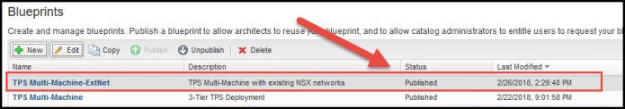
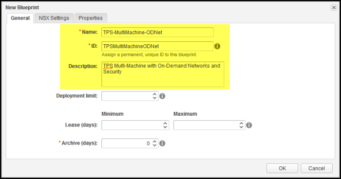
- Navigate to the Design > Blueprints section of vRA 7.3 and click New. Provide a Name (and Description) of the blueprint; select your transport zone one the NSX Settings tab (not pictured) and click OK.
NOTE: The ID dialog box will automatically populate.

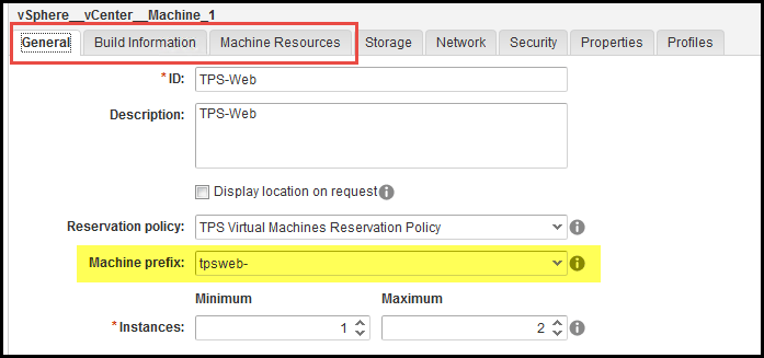
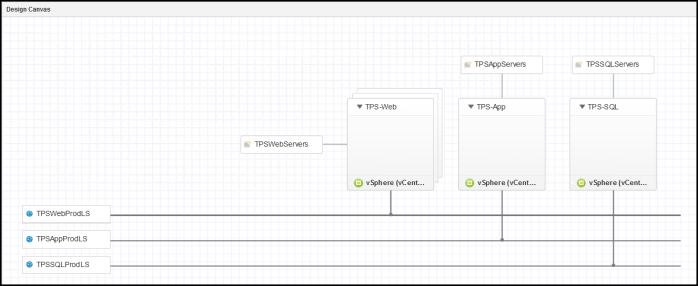
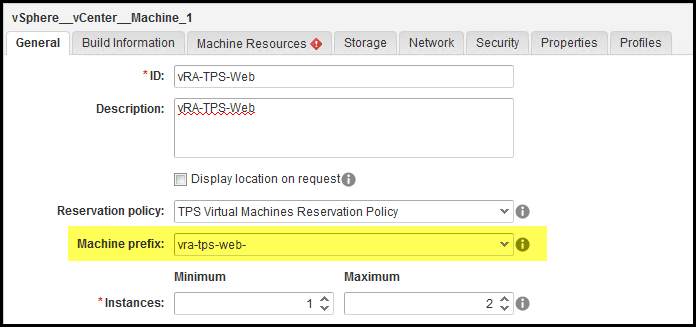
- The design canvas for the blueprint will appear. First let’s add my three (3) VM resources to the canvas and begin configuring how I want my VMs to be deployed for this blueprint. On the General tab I select a few settings that I want and make sure the correct ‘Machine prefix’ is selected. This will be important to ensure my Security settings are properly set when the VM is deployed. Configure everything to your liking on the first 3 tabs. The first VM in my blueprint that I am working with is for my TPS Web VMs.
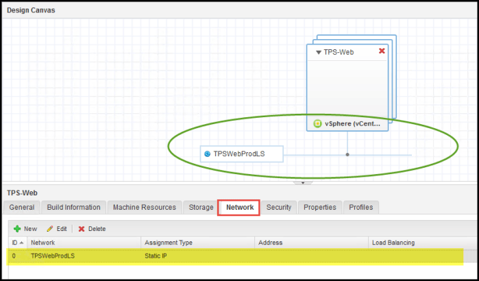
- Next we want to provide the network resources for the TPS Web VMs that I want to deploy. Select Network & Security and then select Existing Network and drag it into the canvas. I then select the ‘TPS-Web-Prod-LS’ network profile that I created earlier and the settings from the profile populate the tabs.
- Next re-select the VM in the design canvas and then select the Network tab below. Click New and then from the drop-down menu under Network choose the network and click OK. The VM resource in your design canvas will now be connected to this network.
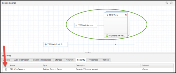
- Next we are going to drag the Existing Security Group component into the canvas and then configure the component to use the TPS Web Servers security group that I pre-configured in my NSX environment and is configured with the dynamic group membership name that uses the same VM machine name prefix.
- Re-select the VM in the design canvas and then select the Security tab. The VM will now attach itself to the Existing Security Group that you just configured in the blueprint.
- I am now going to repeat Steps 1 thru 6 again for my TPS App Servers and TPS SQL Servers. When I am finished my blueprint canvas will look like this. Each VM type (Web, App, SQL) is connected to its respective existing network and will have its respective security group applied. I then click Save and Finish.
- By default your new blueprint is in DRAFT status. Don’t forget that. No one can use this blueprint until it has be published. Also, don’t forget your Entitlements in vRA as well.
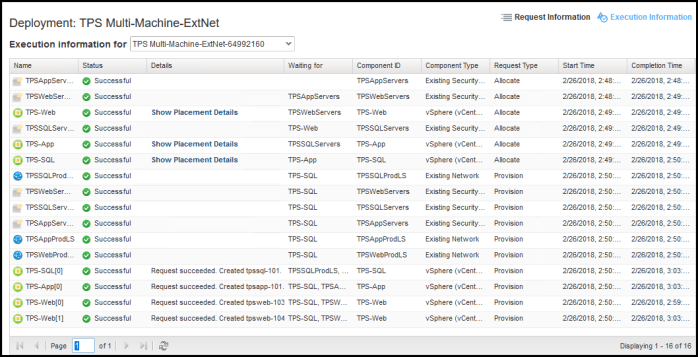
- I then log into vRA with my infamous ‘Bill Lumbergh’ TPS user account and request the new catalog item for my TPS 3-Tier Application and test the deployment. I have a successful deployment confirmed from vRA. I log into vSphere and see that the VMs are powered on and begin other verification procedures that my new VMs are part of the proper Security Groups in NSX and connected to their respective networks.
vRA Blueprint with On-Demand Routed Networks and On-Demand Security Groups
Next we are going to accomplish another vRA deployment task similar to the one we just did except we are going to take the ‘On-Demand’ approach versus using Existing networks or security groups. This is where Security Policies will come into play.
There is one thing I will demonstrate that is different from the previous task where each group of my 3-Tier application (SQL, App, Web) had its own logical switch segment (TCP/IP subnet). In this example I’m going to deploy all of my resources onto the same on-demand routed segment (172.20.100.x) and still enforce the same firewall rules and achieve the same security results. I am able to accomplish this because my firewall rules are not designed to enforce policies based on a specific TCP/IP segment (or legacy VLAN ID approach) or by anything else of that matter. By leveraging NSX Security Groups I am able to create, in essence, logical containers for my VMs and apply security policies to those containers. The underlying networking is no longer a constraint for vSphere Admins or Network Admins. I can accomplish very easily thanks to the flexibility I have when utilizing Security Groups and Security Policies in NSX. They enable you to create and maintain more efficient and dynamic security policies.
Let’s get started on this task.
- Navigate to the Design > Blueprints section of vRA 7.3 and click New. Provide a Name (and Description) of the blueprint; select your transport zone one the NSX Settings tab (not pictured) and click OK.
NOTE: Again, the ID dialog box will automatically populate.
- The design canvas for the blueprint will appear. First let’s add my three (3) VM resources to the canvas and begin configuring how I want my VMs to be deployed for this blueprint. On the General tab I select a few settings that I want and make sure the correct ‘Machine prefix’ is selected. This will be important to ensure my Security settings are properly set when the VM is deployed. Configure everything to your liking on the first 3 tabs. The first VM in my blueprint that I am working first is for my TPS Web VMs (on-demand) which use a different machine prefix as you see below. I explained why earlier on in the blog.
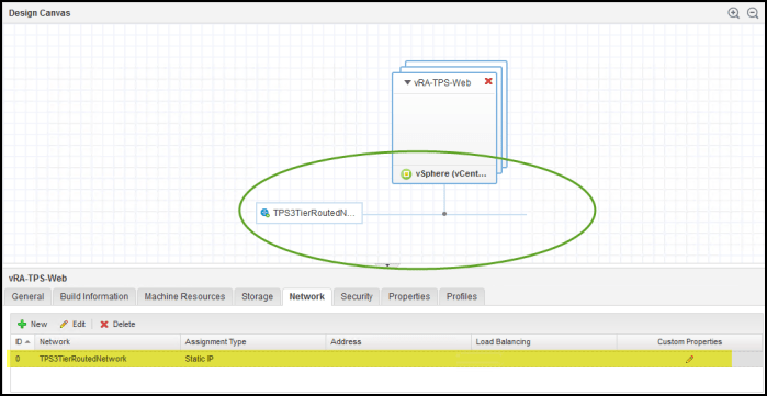
- Next we want to provide the network resources for the TPS Web VMs that I want to deploy. Select Network & Security and then select On-Demand Routed Network and drag it into the canvas. I then select the ‘TPS 3-Tier Routed Network’ parent network profile that I created earlier and the settings from it will populate the tabs below.
- Next re-select the VM in the design canvas and then select the Network tab below. Click New and then from the drop-down menu under Network choose the network and click OK. The VM resource in your design canvas will now be connected to this network.
- Next we are going to drag the On-Demand Security Group component into the canvas. Provide the policy with an ID and then click Add. I then select the TPS Web Policy
- Re-select the VM component in the design canvas and then select the Security tab. Select the check box next to the new security policy.

- I am now going to repeat Steps 1 thru 6 again for my TPS SQL Servers and TPS App Server. Each VM type (Web, App, SQL) is connected to the same On-Demand Network. The only difference is the On-Demand Security Policies are only for the Web and SQL tiers. The app tier will be configured to use an Existing Security Group. I will explain in greater detail once everything is deployed as it will be easier to understand. When I am finished my blueprint canvas will look like this. Click Save and Finish.

- Again, by default your new blueprint is in DRAFT status. Don’t forget that. No one can use this blueprint until it has be published. Also, don’t forget your Entitlements in vRA as well.

- I then log into with my infamous ‘Bill Lumbergh’ TPS user account and request the new catalog item for my On-Demand TPS 3-Tier Application and test the deployment. I have a successful deployment confirmed from vRA. I log into vSphere and see that the VMs are powered on and begin other verification procedures that my new VMs are part of the proper Security Groups in NSX and connected to their respective networks.
- In vRA the Bill Lumbergh user account can now view his deployment and connect to his new VMs.

Now the the deployment is complete let’s go back and review why I designed blueprint VMs the way I did (Reference Step 7). Specifically with the vRA TPS Web and vRA TPS SQL virtual machines using ‘On-Demand Security Groups’ and the vRA TPS App virtual machine configured with an Existing Security Group. The reason I did this was because of how I intended to design the security policies.
My goal was to illustrate how I can utilize security policies to achieve the same end result as earlier when I manually configured the rules. The following screenshot displays those manually create rules for my 3-tier TPS application.

And another summary of what these rules are accomplishing:
- Permit TPS App to TPS SQL for the APP_MYSQL service.
- Permit TPS Web to TPS App for the customized TPS_Tomcat_APP.
- Permit ANY to the TPS Web for APP_HTTPS_SSL_V3.
- TPS Web Micro-segmentation to the TPS Web Servers to BLOCK all communication with one another.
I design my security policies to enforce the same rules. I am able to do this very efficiently because most of my rules focus around one group of VMs in particular…the Web VMs. Three (3) of the four (4) rules I am enforcing have the Web VMs in the source, destination or both. I can accomplish this using a Security Policy with the following settings.

I then apply that policy to a Security Group that was created previously. One was applied manually when I was accomplishing a different task in my lab but as you can see the other was applied during the vRA deployment.

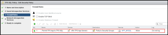
The TPS SQL Policy is very simple and contains a single firewall rule as you can see below.
Now lets take a look at how Service Composer creates and enforces the rules for the DFW. As you can see the rules being enforced are achieving the same end result (seen below). The TPS App Servers configured in my blueprint are to use an ‘Existing Security Group’ which will simply place those specific VMs into the ‘vRA TPS App Servers’ security group. You will notice the ‘vRA TPS App Servers’ Security Group are defined in both Security Policies. This ensures my DFW rules will be applied to those VMs even though I did not create or apply a security policy specifically to those systems.
Back to my goal for deploying On-Demand Routed Networks and On-Demand Security Groups I needed to do a few things.
- In vRA: Create a ‘Routed Network Profile’ for the ‘On-Demand Routed Network’ that will be deployed during my workflow which will be defined in a vRA blueprint.
- In NSX: Create Security Policies in NSX Service Composer. This will enable an admin to utilize the ‘On-Demand Security Group’ component in a vRA blueprint.
Here are the manually created rules and the NSX Service Composer Security Policy rules side-by-side for comparison.
Now don’t get confused and think you need to do both in order to accomplish everything above. I want to simply demonstrate that you can achieve firewall enforcement in one of two ways. Personally I like using policies but in some instances you need to create a manual DFW rule.
It is possible to create a blueprint in vRA with External Networks and On-Demand Security Groups as long as you have the NSX Service Composer Policies in place. That’s all there is to it. Software-defined policies are super friendly when it comes to automation.
Conclusion
As I stated earlier automation makes our lives easier. If you find yourself doing tasks repetitively day-in and day-out with long procurement cycles then you are probably a candidate for automation. If the organization you work for has a high-demand for IT resources and have that “needed it yesterday” mentality then start looking more into automation to solve your problems. Together vSphere, vSAN, NSX and vRealize Automation provide the ability to provision and configure all of the resources in your virtual infrastructure.
There are also other great tools in the VMware arsenal that will help you on your journey to automation and help plan this infrastructure to run efficiently for you.
vRealize Network Insight (vRNI) will help you observe existing network traffic in vSphere. The information it provides you can then be used to help plan and design your NSX networks and firewall rules!! It literally tells you the traffic (source to destination) and the specific applications and port numbers to include in your DFW rules. Doesn’t get much simpler than that!
vRealize Operations Manager (vROPs) can assist vRealize Automation during workload placement and provide ‘Placement Details’ for the VMs that are being provisioned.
vRealize Log Insight (vRLI) collects logs from just about everything…vSphere, NSX, vRA, vROPS and 3rd party. Content Packs are available from the VMware Solutions Exchange for just about everything. vRLI will not only provide a central repository for collecting your logs but also speed up troubleshooting and determining root cause analysis during failures and other events.
Hope you enjoyed this lengthy blog! If you have any questions please reach out and comment below.
Useful Links
VMware vRealize Automation Docs (7.1 – 7.3)
Configuring vRealize Automation 7.3 (January 2018) (PDF) – Highly recommend reading this one!

Extremely helpful. I have a lab with vRA 7.3 and NSX 6.4 and this blueprints are very insightful. Already deployed dynamic Routed networks with load balancer and it just works.
I want to achieve the following: give the user the posibility to request an On-Demand Routed Network and On-Demand security group, without anything in it. This part is simple, I have a blueprint that creates a new network and it runs fine.
Then, I want to give him the ability to deploy VMs to their liking on the networks that he requested earlier.
Do you know how can it be done?
LikeLike
Why would you want to permit an end user to choose their network? Isn’t part of the idea of using blueprints is to ensure workloads are placed where an administrator wants them to reside and guarantee they are inheriting the proper security parameters, network settings, etc.? I don’t see the benefit of allowing end users to choose “where they want” to place their workloads. You’re the admin, you decide in the blueprint where the workload needs to be based on your requirements.
LikeLike
You would give them like a /16 range for a number of networks they can provision. You can filter the ones you want to route to the external world, and the ones you dont, that way you get a AWS-like experience in your DC… basically, what the consumers want. Goes without saying that you should secure what these have access to… I mean, you’re the one who defined the /16, so…
LikeLike
Pretty
LikeLike